19
20
7
Debugging
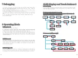
1) Close the DC switch on the inverter. As long as the input DC voltage is greater than
250V, the inverter display will display the following message: There is no AC connection
error, the inverter LED will turn red.
If other information is displayed, please refer to Chapter 9. If you encounter problems
during the debugging process, please contact customer service.
2
)
Close the circuit breaker or switch between the inverter and the grid. The inverter
starts the self-test countdown. After the self-test is normal, it will be connected to the
grid.
3
)
In normal operation, the leaves of the inverter indication window will turn green.
4
)
Complete debugging.
8
Operating Mode
8.1 Normal mode
In this mode, the inverter works normally.
When the DC voltage is greater than 250V, the energy is sufficient and the grid
voltage frequency meets the requirements of grid connection, the inverter converts the
energy of the solar panel into an AC input grid, and the green LED lights up.
When the DC voltage is lower than 180V, the inverter will automatically disconnect
from the grid and exit the normal operation mode. When the input voltage reaches the
requirement again and the grid voltage returns to normal, the inverter will automatically
connect to the grid.
Ø
Ø
8.2 Failure mode
The inverter control chip monitors and adjusts the status of the system in real time. When
the inverter monitors any unexpected conditions, such as system failure and inverter
failure, the fault information will be displayed on the display. In the fault mode, the
inverter indicates The leaves of the window turn red and the inverter output is
disconnected from the grid.
When the light is weak or there is no sunlight, the inverter will automatically stop
running. When in the shutdown mode, the inverter basically does not consume the
energy of the grid or solar panels, and the inverter display and LED lights are turned off.
8.3 Shutdown mode
The OLED display can display the operating status of the inverter and various parameter
information. The touch panel can be used to switch the display interface of the inverter
and set the inverter parameters.
OLED Display and Touch Buttons 9
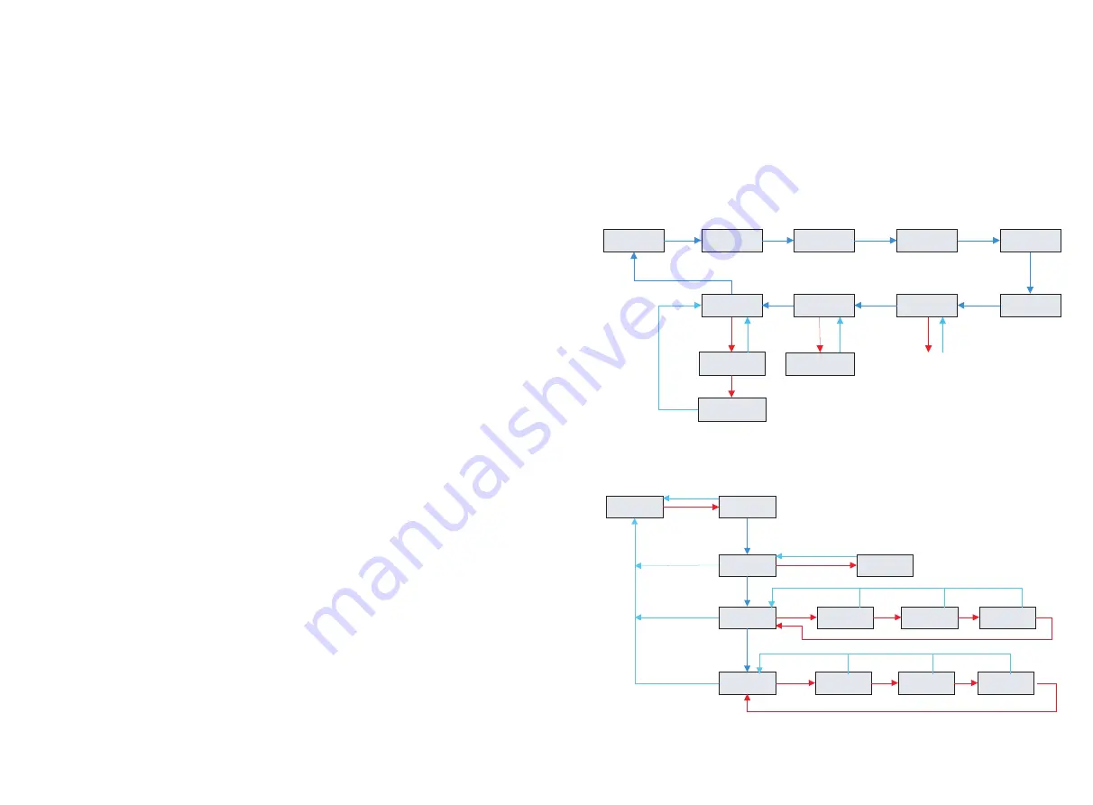
9.1 Boot display
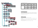
9.1.1 The inverter information interface is as follows
(The dark blue arrow is click--the next page, the red arrow is the double-click--the sub-
menu enters, the blue arrow is the triple-click--back)
POWER
54.6w
Daily
0.8kwh
Total
54.6w
AC
225.7V 50.0Hz
PV1
3.0V 0.0W
PV2
3.0V 0.0W
Energy storage
information
Parameter
settings
More
information
General/Advanced
settings
Model:
A0B1D0T0PFU8M6S1
Firmware Version
Vaaa33
9.1.2 Parameter setting (general settings)
General
settings
Language
settings
Chinese
Address
setting
001
Date setting
16
:39:50
Date setting
2019-06-12
Address
setting
001
Date setting
2019
-06-12
Date setting
2019-
06
-12
Date setting
2019-06-
12
Date setting
16:
39
:50
Date setting
16:39:
50
Date setting
2019-06-12


