7
8
4
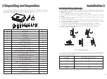
Unpacking and Inspection
Before opening the inverter package, please check the outer packaging for damage.
After unpacking, check the inverter for damage or missing accessories. In the event of
damage or missing accessories, please contact your dealer.
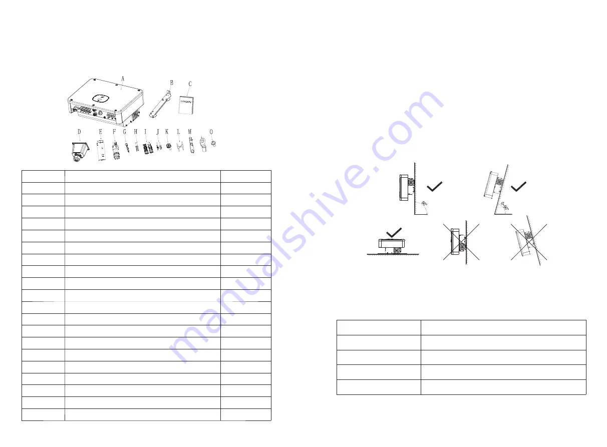
Numbering
Description
Quantity
A
Inverter
1
B
Wall bracket
1
C
quick guide
1
D
AC Waterproof cover
1
E
Collector (optional)
OPT
F
COM port signal connector
2
G
Self-tapping screw
4
H
Plastic expansion tube
4
I
PV+/PV- Terminal (25k model 5/5PCS)
4/4
J
PV+/PV- Metal terminal (25k model 5/5PCS)
4/4
K
Safety screw
1
L
Signal connector unloading tool
1
M
PV Terminal removal tool
1
N
14-6 O-type terminal
6
O
Fixed AC waterproof cover M4*10 screw
4
*
Warranty card
1
*
A copy of the business license
1
*
Certificate
1
*
Packing List
1
*
CQC report and certificate
1
Installation 5
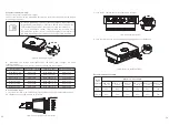
5.1 Basic installation requirements
Ø
The wall on which the inverter is mounted must be sturdy and can withstand the
weight of the inverter for a long time (refer to the specifications in Chapter 12 for the
weight of the inverter);
Ø
The installation location must match the size of the inverter;
Ø
Do not install the inverter on a building constructed of flammable or heat-resistant
materials;
Ø
Install the inverter in an eye-view orientation to facilitate inspection of the OLED
display and maintenance work;
Ø
The machine's degree of protection is IP65 and can be installed indoors and outdoors;
Ø
It is not recommended to expose the inverter directly to strong sunlight to prevent
overheating and cause power derating;
Ø
The humidity of the installation environment should be between 0 and 90%;
Ø
The ambient temperature around the inverter should be between -25 ° C ~ 60 ° C;
Ø
The inverter can be mounted on a plane that is tilted vertically or backwards.
Please refer to the following figure:
Ø
In order to ensure the normal operation of the machine and the convenience of
personnel operation, please pay attention to provide sufficient clearance for the inverter.
Please refer to the figure below:
Direction
Minimum clearance (mm)
Above
300
Under
500
Both sides
500
Forward
300
fig5
.
1
Installation diagram
N

