23
24
Fig 6.15
Fig 6.14
Fig 6.16
6.5 Grounding the inverter
The inverter must be connected to the AC grounding conductor of the power distribution
grid via the ground terminal (PE) .
WARNING
WARNING
Because of the transformerless design, the DC positive pole and DC
negative pole of PV arrays are not permitted to be grounded.
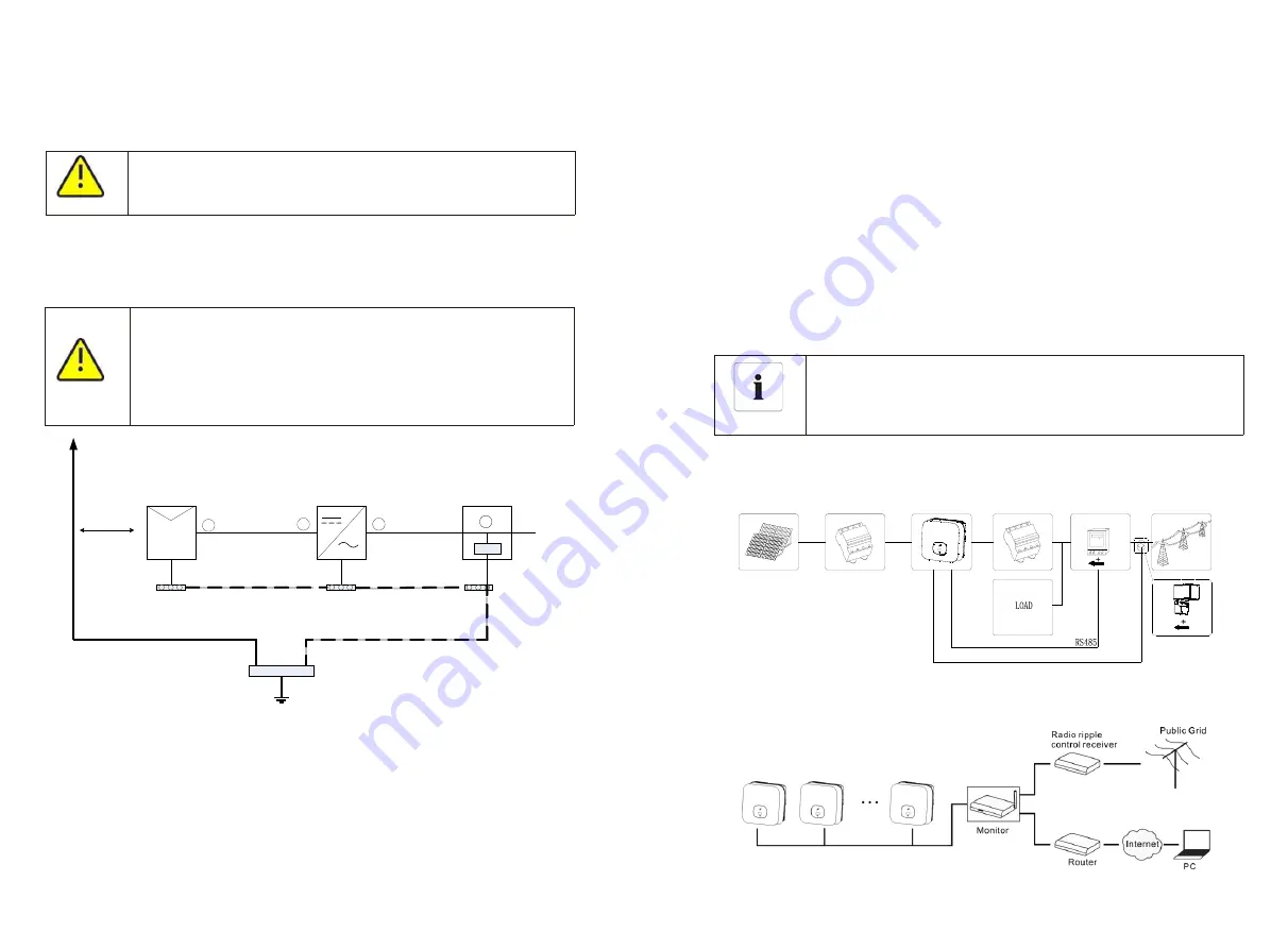
6.6 Active power control with smart meter , CT or ripple control
signal receiver
Information
The position of export limitation CT or Meter must between the
Inverter & Load and gird.
This series inverter has integrated export limitation functionality. To use this function,
you can connect smart meter or CT. The smart meter model is Eastron SDM230-Modbus.
The CT Model is TOP 90-S10/SP4(LEM).The primary aperture is 10mm,output cable
length is 5m . The arrow on the CT must pointing towards the inverter.
Active power control with a Radio Ripple Control Receiver(RRCR).
According to the relevant provisions of IEC 61643-32 "Connecting to photovoltaic
devices surge protectors - selection and use of guidelines", whether for household or
outdoor photovoltaic power plants, it is necessary to ensure the implementation of
lightning protection measures for photovoltaic systems:
The lightning protection measures for photovoltaic systems shall be
carried out in accordance with the corresponding national standards
and IEC standards. Otherwise, photovoltaic devices such as
components, inverters and power distribution facilities may be
damaged by lightning.
In this case, the company does not carry out warranty and assumes
any responsibility.
Photovoltaic panel
Inverter
Distribution
Cabinet
SPD
Power grid
Lightning
protection device
Grounding bar
1
2
3
4
Total grounding point
L
ig
h
tn
in
g
d
o
w
n
th
e
li
n
e
Equipment ground wire
Lightning down the line
Safety
interval S
1
)
It is generally recommended to install lightning protection devices (such as lightning
rods / lightning protection belts and down conductors) to prevent lightning from hitting
the PV array.
2
)
Lightning protection devices and down-conductors and related equipment in
photovoltaic systems (including photovoltaic panels, inverters, cables, power
distribution equipment) should maintain a safe separation distance S.
Suggested value of S: According to the general 5 storey height (about 15m) building
roof, S takes 2.5m enough, this distance can be simplified according to the inverse
relationship of the floor height.
A. When the safety distance S is satisfied
:
The position
① ③
of the figure should be equipped with a lightning protection module.
In general, it is recommended to install Type II in position
①
and Type I in position
③
.
B. When the safety and safety distance S is not met
:
In addition to position 3, Type I lightning protection module should be installed in Figure
①②④.
3
)
The lightning down conductor and the equipment ground wire eventually sink at a
total ground point, but the two cannot share the wire. That is, the equipment grounding
wire should be pulled separately, and the wire diameter requirement >6mm
²
when the
safety interval distance S is satisfied.
4
)
About the above lightning protection lightning receptor system related design
reference GB/T 21714.3-2015
.


