19
20
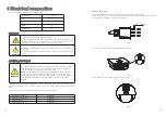
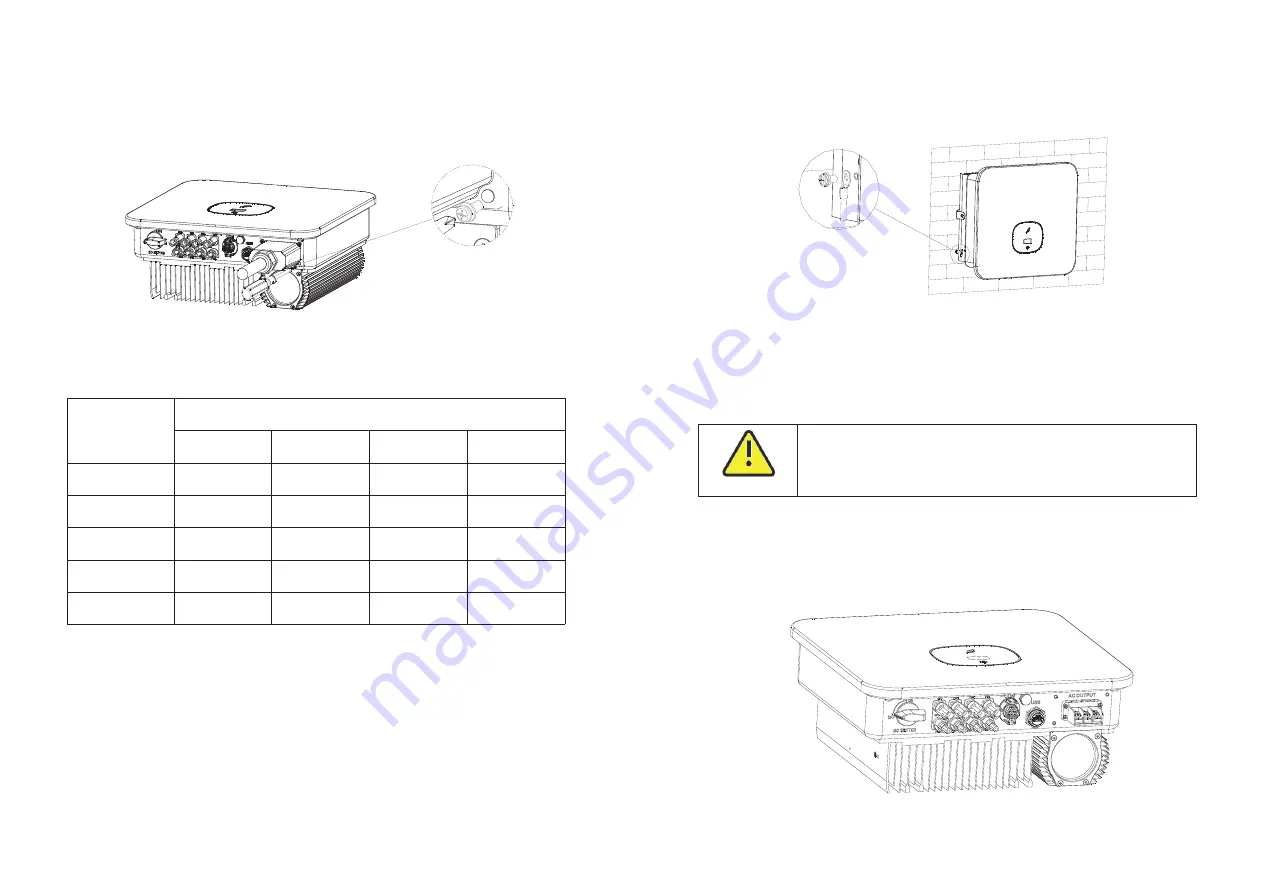
5.Finally, Lock the protective cover on the inverter frame, and finally tighten the
protective cover hole.
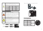
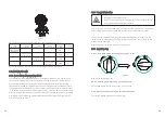
Wire suggestion length
Conductor cross
section
Max. cable length
MIN
7000 TL-X/X(E)
1 AWG
0
6AWG
4 m
2
AWG
9
8AWG
7AWG
MIN
8000 TL-X/X(E)
MIN
9000 TL-X
MIN
10000 TL-X
53m
67m
85m
107m
37m
47m
59m
74m
93m
33m
41m
52m
66m
83m
30m
37m
47m
59m
75m
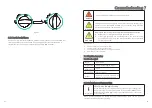
Fig 6.4
6.3 Connecting the second protective conductor
In some installation countries, a second protective conductor is required to prevent a
touch current in the event of a malfunction in the original protective conductor.For
installation countries falling within the scope of validity of the IEC standard 62109, you
must install the protective conductor on the AC terminal with a conductor cross-section
of at least 10 mm²Cu.Or Install a second protective conductor on the earth terminal with
the same cross-section as the original protective conductor on the AC terminal. This
prevents touch current if the original protective conductor fails.
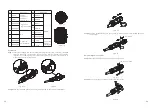
Fig 6.5
6.4 Connecting the PV Array (DC input)
6.4.1
Conditions for DC Connection
WARNING
WARNING
The solar modules connected to the inverter must conform to the
Class A requirements of the IEC 61730 standard.
Please use the same brand male and female PV connectors.
The MIN 7000-10000TL-X single-phase inverter has 3 independent input : MPPT1,
MPPT2 & MPPT3.
The MIN 7000-8000TL-X(E) single-phase inverter has 2 independent input : MPPT1 &
MPPT2.
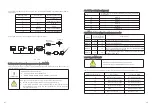
Notice that the connectors are in paired (male and female connectors).
Fig 6.6


