23
24
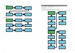
Procedure
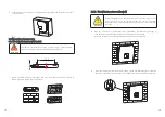
Step 1
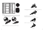
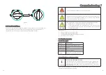
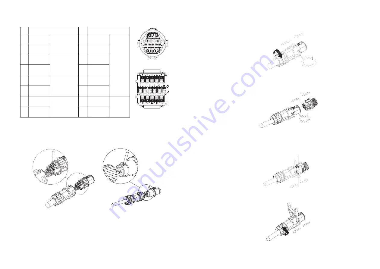
sleeve in sequence, insert cables into connection terminal according to number
indicates on it and tighten the screws firmly. Please try to pull out the wire to
make sure the it's well connected.
Insert the stripped and bared cable through pressure screw, seal ring, threaded
Step 2
Push the threaded sleeve into the socket, Tighten up the cap on the terminal.
Step 3
the inverter.
Push the threaded sleeve to connection terminal until both are locked tightly on
Uninstall signal connector
Step 1
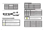
Press the fasteners and pull it out from the inverter.
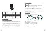
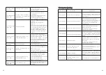
NC
No.
Definition
1
2
3
4
+12V
COM
RS 485A1
RS 485B1
Power
supply for
external
relay(
≤
2W)
Signal for
communication
No.
Definition
10
9
11
12
DRM 7
DRM 8
DRM 5
DRM 6
5
6
7
8
CT-P
CT-N
RS 485B2
RS 485A2
Signal for
export
limitation
Signal for
Smart Meter
13
14
15
16
RefGen
Com/DRM0
-
-
DRMS
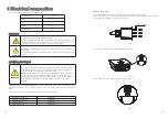
Fig 6.11
Fig 6.13
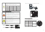
Fig 6.15
Inverter side
Click!
Fig 6.16
Fig 6.17
Click
!
The
Inverter
Side
Fig 6.12
Fig 6.14
Step 2
Insert the H type tool and pull it out from the socket.
Fig 6.18


