GR
-
UM
-
162
-
A
-
02
Download
Manual
Growatt New Energy
5.
Verifying the Installation
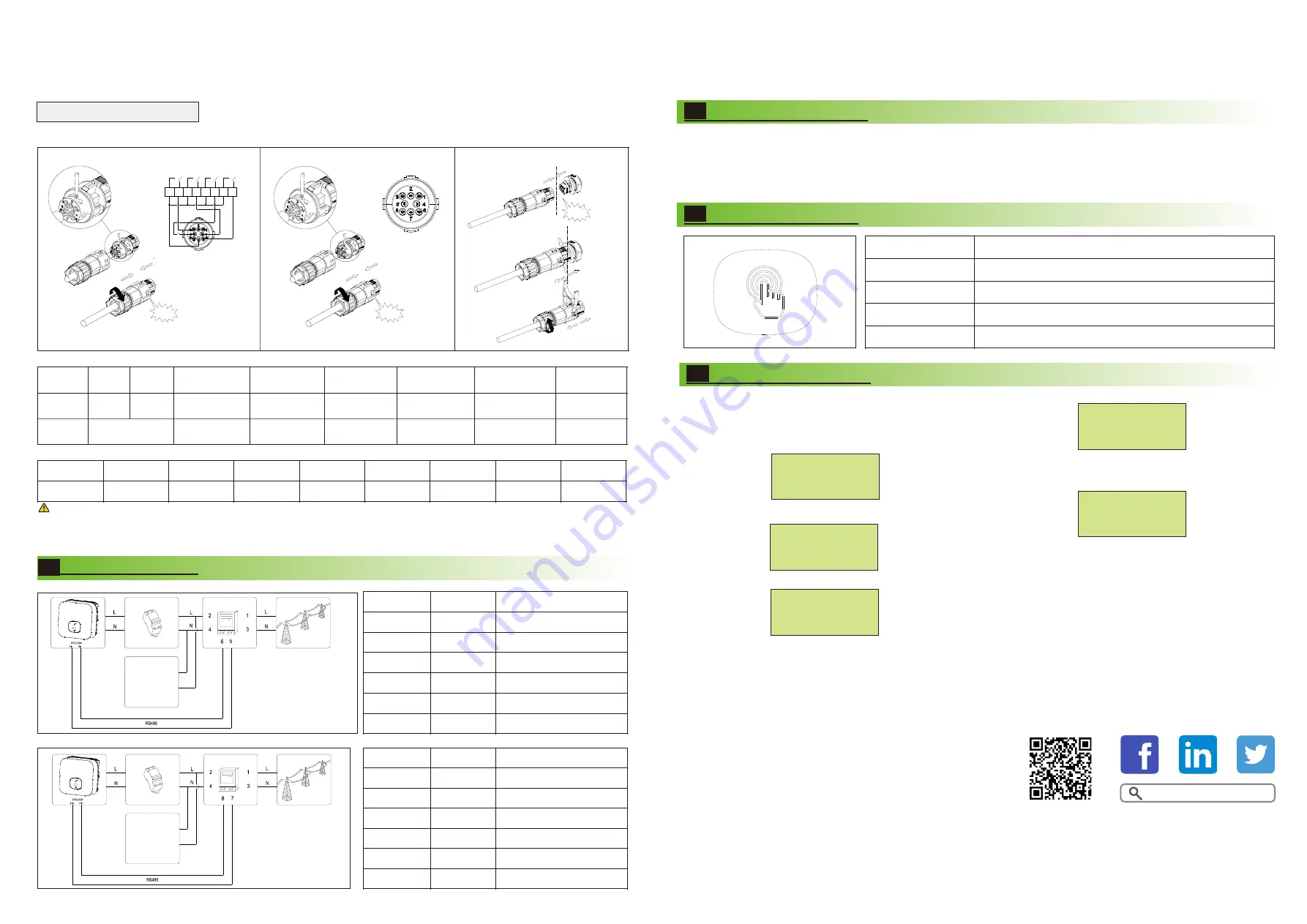
1.When laying out signal cables, separate them from power cables to avoid strong signal interference sources.
2.Do not confuse the connector to the COM port and the connector to the SYS COM port.
3.The COM port Aonly provides a functional port-PCI or DRM.
Notice
:
The Inverter
side
The Inverter
side
Unclock the housing
European
Australia
NO
1
2
3
4
Function
Connect
to RRCR
+12V
GND
Not connected
Relay contact
2 input
Relay contact
3 input
Relay contact
4 input
GND
Relay contact
1 input
Not connected
Not connected
K2- output
K3- output
K4- output
Relays common
node
K1- output
5
6
7
8
COM Port Pin Definitions- Power Control Interface(PCI).
COM Port Pin Definitions- DRED connection
+12V
Function
DRM3/7
DRM4/8
REFGEN
COM/DRM0
DRM1/5
DRM2/6
GND
NO
5
6
7
8
1
2
3
4
7.
Powering On the System
Step2: Turn on the AC switch between the Min 2500-6000TL-XH and
the power grid.
Step3: When the OLED show ”Country/Area VDE0126”, Please Set the
country follow the below step4.
Step4: Single touch to switch Country, such as N4105, Then jump to step6.
Step5: Single touch to switch Country, such as Newzealand.
When the OLED show ”Country/Area Australia”, Please Set the country
follow the step5
Step6: Press the touch key for 5s or No operation on the OLED
for more than 30S (The country of the current interface is
selected by default)the OLED shows Country setting is complete.
If the LED light is green, the system is operating normally.
You can reset the country by “Set Country” in the submenu of “Set
parameter”.
3.5 Installing the COM Signal Cable
We use 8Pin COM Port Connector as Power Control Interface(PCI) for European models or Connector as inverter DRED connection(DRM)
for Australia.
Connecting Meter
4.
The following table describes how we can connect EASTRON meter (SDM230-Modbus)to inverter:
The following table describes how we can connect CHINT meter (DDSU666) to inverter:
Tips
Meter Pin NO.
Description
Connect to Inverter
1
2
3
4
5
6
L-in
L-out
N-in
N-out
RS485A
RS485B
/
AC connector & Load L
/
AC connector & Load N
SYS COM Pin 5 RS485A1
SYS COM Pin 6 RS485B1
Meter Pin NO.
Description
Connect to Inverter
1
2
3
4
7
8
L-in
L-out
N-in
N-out
RS485A
RS485B
/
AC connector & Load L
/
AC connector & Load N
SYS COM Pin 5 RS485A1
SYS COM Pin 6 RS485B1
5
6
Country/Area
Australia
Country/Area
N4105
Country/Area
N4105
Country/Area
Newzedland
Country/Area
VDE0126
Set OK
Step1: Turn on the DC switch at the bottom of the Min 2500-6000TL-XH.
6.
1.The Min 2500-6000TL-XH is installed correctly and securely.
2.The Monitor is installed correctly and securely.
3.The Ground cable is connected correctly and securely.
4.The DC switch and all the switches connecting to the Min 2500-6000TL-XH are OFF.
5.The AC output power cable, PV&BAT input power cable and signal cable are connected correctly and securely.
6.Unused terminals and ports are locked by watertight caps.
Button touch operation
Touch button
Single touch
Double touch
Three touch
Hold 5s
Description
Switch display or 1
Enter
Previous menu
Confirm country setting or Number recover defaut value
Click!
Click!
Click!
RRCR
PCI Connector
K1
K2
K3
K4
1
2
3
4
5
6
7
8
5
6
LOAD
LOAD
Shenzhen Growatt New Energy Co., Ltd
4-13/F,Building A,Sino-German(Europe) Industrial Park,
Hangcheng Ave,Bao’an District, Shenzhen, China
+86 0755 2747 1942
www.ginverter.com
T
E
W
service@ginverter.com


