Installing the Device
Connecting Cables
3.1
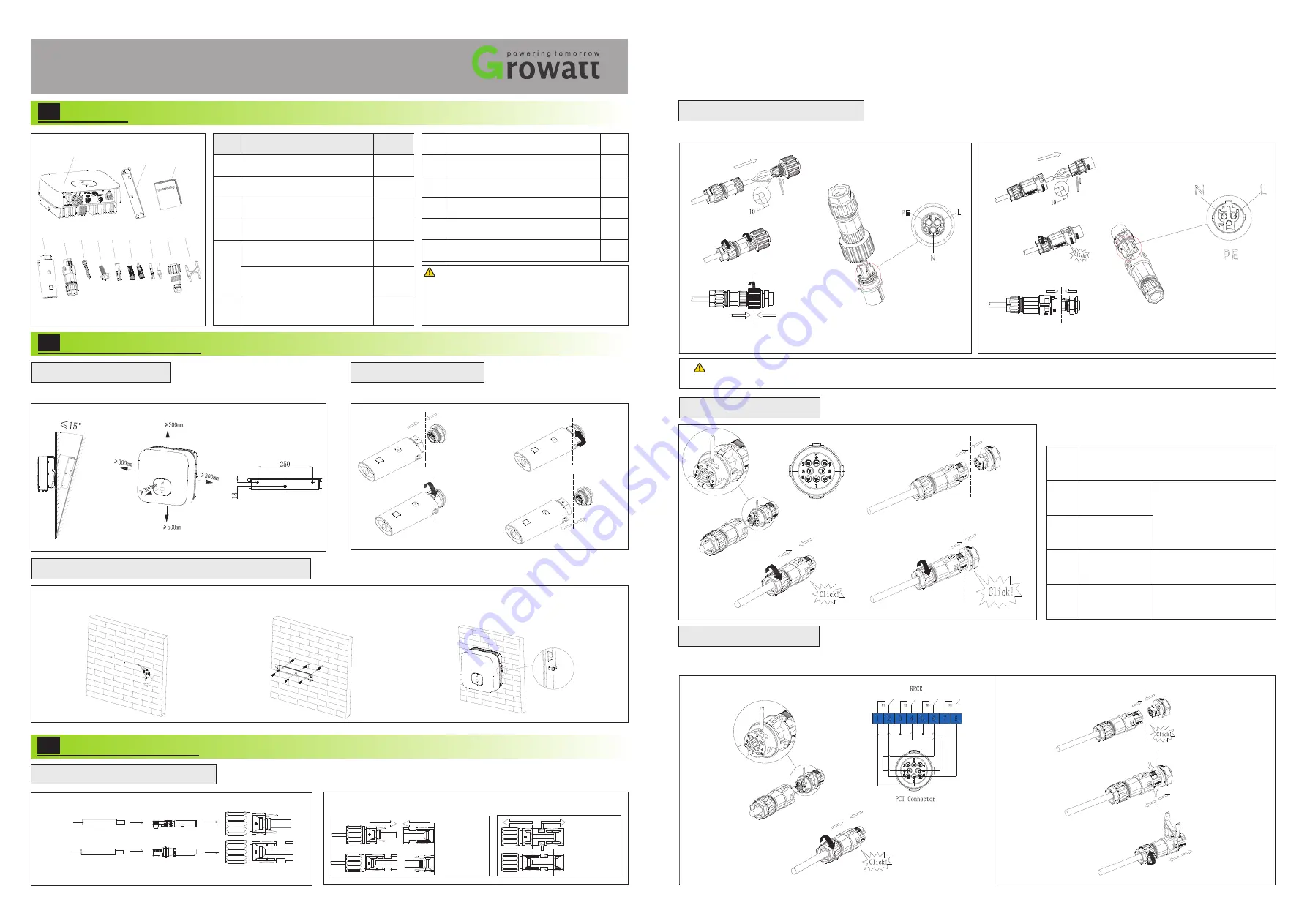
Installing the PV Input Power Cable
Cables
Cables
Positive metal
terminal
Positive connector
Negative connector
Negative metal
termina
4~6mm²
4~6mm²
The Inverter
Side
Pull the PV input power cable back to ensure that it is connected securely.
The Inverter
Side
2
.
3
Installing
the
Monitor
2.2 Installing the Mounting Bracket And Min 2500-6000 TL-XE
Install
Remove
Ensure that the Monitor is installed securely.
Fix the wall bracket
Installation & Tighten
screw assemblies
The
Inverter
Side
The
Inverter
Side
The
Inverter
Side
The
Inverter
Side
Overview
2.
2
.
1 Installation Requirements
Tilt and Space
Drilling holes
1.
3.
MIN 2500-6000 TL-XE
Quick Guide
Description
A
Inverter
1
B
Mounting bracket
1
C
Quick Guide
1
D
Monitor(Optional)
1
E
Notice
:
A
B
C
D
E
F
G
H
J
K
L
I
PCI connector
Before installing the device,check that the pack-
age contents are intact and complete against
the packing list.If any damage is found or any c-
omponent missing,contact your dealer.
Object
Quantity
Signal connector
G
Safety-lock screw
1
H
Plastic expansion pipe
3
I
PV+/PV- terminal
2/2
J
PV+/PV- metal terminal
2/2
K
AC connector
1
L
Uninstall signal and AC connector tool
1
F
3
Self-tapping screws
1
1
3.3
Installing the Signal Cable
3.4
Installing the PCI Cable
The
Inverter
side
The
Inverter
side
SYS COM Port Pin Definitions
Definition
NO.
3
4
5
6
RS485A2
RS485B2
AntiReFlux
-
A
AntiReFlux
-
B
Signal
for
RS485
RS485A
for
meter
or
CT-P
RS485B
for
meter
or
CT-N
We use 8Pin COM Port Connector as Power Control Interface(PCI) for European models.
The
Inverter
side
The
Inverter
side
Unclock the housing
European
L ----
Line
N ---- Neutral
PE ---- Ground
3.2
Installing the AC Output Power Cable
Connect the AC output power cable to the AC connector.
Notice
:
Suggest using 6mm
²
cables. Ensure the exposed core wire is totally inserted into the cable hole and connected securely.
Type 2
L ----
Line
N ---- Neutral
PE ---- Ground
The Client Side
The Inverter Side
Lock the housing
Type 1
The Inverter Side
Lock the housing
The Client Side


