32
31
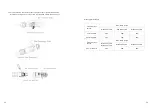
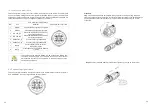
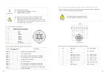
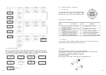
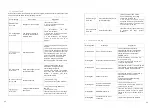
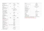
6.9.2.2 The inverter is preconfigured to the following RRCR power levels
PCI Connector(SYS COM PORT)
Active power
Cos(φ)
Pin 3
Pin 4
Pin 5
Pin 6
Short circuit
with Pin7
0%
1
Short circuit
with Pin7
30%
1
Short circuit
with Pin7
60%
1
Short circuit
with Pin7
100%
1
Active power control and reactive power control are enabled separately
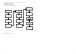
6.10.3 Operation step
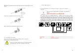
When the inverter error 200, please follow the steps:
Step1: Cut off all power supply connection of the inverter. Turn off the Battery input switch, turn off the
inverter's AC output breaker, turn off the PV input Switch, wait for the display to go out;
Step2: Perform troubleshooting on the system, Check all PV strings for the correct open- circuit
voltage;
Step3: After the fault is rectified, restart the inverter. Turn on the Battery input switch, turn on the the
inverter's AC output breaker,
turn on the PV input Switch
, Waiting for the system to work properly
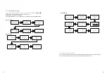
If the AFCI self-
test is successful, the inverter will switch into the “nominal” mode and the green LED is
permanently lit.
If the AFCI self-
test is failed, the following message appears on the display: “Error 425”, please restart
the system, repeat step1 to step3.If the AFCI self-test continues to fail,cut off all power supply
connection of the inverter,and contact Growatt to solve this problem
6.10
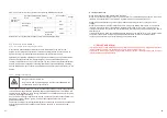
Electric arc hazards
6.10.1
Arc-Fault Circuit Interrupter(AFCI)
In accordance with the National Electrical Code R, Article 690.11, the inverter has
asystem for the recognition of electric arc detection and interruption. An electric arc with
a power of 300 W or greater must be interrupted by the AFCI within the time
specified by UL 1699B. A tripped AFCI can only be reset manually. You can deactivate the
automatic arc fault detection and interruption (AFCI) via a communication product in
"Installer" mode if you do not require the function. The 2011 edition of the National Electrical
Code R, Section 690.11 stipulates that newly installed PV systems attached to a building
must be fitted with a means of detecting and disconnecting serial electric arcs (AFCI) on the
PV side.
6.10.2
Danger information
The inverter has double MPPTs, it is recommended for each MPPT to work independently, do
not use parallel wiring at DC side (Parallel wiring can make 2 MPPTs become 1 MPPT, this
can improve the efficiency in some cases). If the MPPTs are parallel wired at inverter it may
cause the AFCI trigger mistakenly.
If an "Error 200" message is displayed, the red LED is permanently lit and the buzzer alarms, an
electric arc occurred in the PV system. The AFCI has tripped and the inverter is in
permanent shutdown.
The inverter has large electrical potential differences between its conductors. Arc flashes can
occur through air when high-voltage current flows. Do not work on the product during
operation.
6.11
Earth Fault Alarm
The inverter complies with AS/NZS 5033.The installer does not need to perform any additional actions,
as this is already set up.When the Earth fault occurs,the Red LED will light up.
The buzzer in the inverter will keep ringing unless the fault condition is cleared(This function is only avi
lable for Australia and New Zealand).
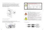
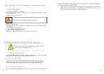
Danger of fire from electric arc
Only test the AFCI for false tripping in the order described below. Do
not deactivate the AFCI permanently.


