background image

4


3


1.5


Glossary 

AC


Abbreviation for "Alternating Current"


DC


Abbreviation for "Direct Current"


Energy


Energy is measured in Wh (watt hours), kWh (kilowatt hours) or MWh (megawatt hours). The 
energy  is the  power  calculated  over  time.  For  example,  your inverter  operates  at  a constant 
power of 4600 W for half an hour and then at a constant power of 2300 W for another half an 
hour, it has fed 3450Wh of energy into the power distribution grid within that hour.


Power


Power  is  measured  in  W  (watts),  kW  (kilowatts)  or  MW  (megawatts).  Power  is  an 
instantaneous  value.  It  displays  the  power  your  inverter  is  currently  feeding  into  the  power 
distribution grid.


Power rate


Power  rate  is  the  radio  of  current  power  feeding  into  the  power  distribution  grid  and  the 
maximum power of the inverter that can feed into the power distribution grid.


Power factor


Power  factor  is  the  ratio  of  true  power  or  watts  to  apparent  power  or  volt  amps.  They  are 
identical only when current and voltage are in phase than the power factor is 1.0. The power 
in an ac circuit is very seldom equal to the direct product of the volts and amperes. In order to 
find the power of a single phase ac circuit the product of volts and amperes must be multiplied 
by the power factor.


PV


Abbreviation for photovoltaic.


Wireless communication


The external wireless communication technology is a radio technology that allows the 
inverter and other communication products to communicate with each other. The external 
wireless communication does not require line of sight between the devices and it is 
selective purchasing.


2


Safety 

2.1


Intended Use 

The  unit  converts  the  DC  current  generated  by  the  photovoltaic  (PV)  modules  to  grid- 
compliant  alternating  current  and  performs  single-phase  feed-in  into  the  electricity  grid.MIN 
2500TL-XH, MIN 3000TL-XH, MIN 3600TL-XH, MIN 4200TL-XH, MIN 4600TL-


XH, MIN 5000TL-XH, MIN 6000TL-XH inverters are built according to all required safety rules. 
Nevertheless, improper use may cause lethal hazards for the operator or third parties, or may 
result in damage to the units and other property.


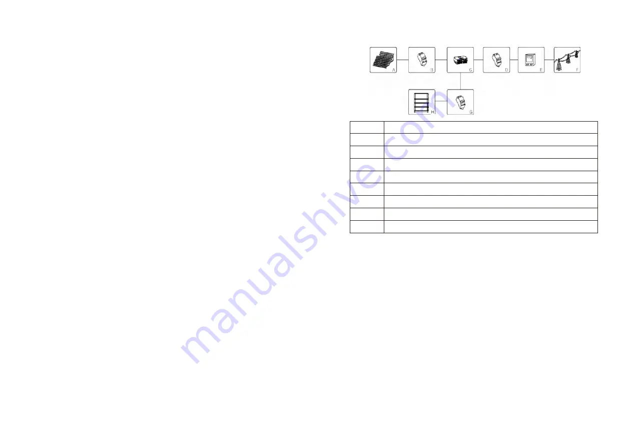
Principle of a PV plant with this MIN TL-XH single-phase inverter


Position


Description


A


PV modules


B*


DC load circuit breaker


C


Inverter


D


AC load circuit breaker


E


Energy meter


F


Utility grid


G


DC load circuit breaker


H


Battery matched with XH inverter


* According to local regulations or installation requirements to choose DC isolator or DC 

load circuit breaker.


The inverter may only be operated with a permanent connection to the public power grid. 
The inverter is not intended for mobile use. Any other or additional use is not considered the 
intended use. The manufacturer/supplier is not liable for damage caused by such unintended 
use. Damage caused by such unintended use is at the sole risk of the operator.


PV modules Capacitive Discharge Currents


PV modules with large capacities relative to earth, such as thin-film PV modules with 
cells on a metallic substrate, may only be used if their coupling capacity does not exceed 
1uF. During feed-in operation, a leakage current flows from the cells to earth, the size of 
which depends on the manner in which the PV modules are installed (e.g. foil on metal 
roof) and on the weather (rain, snow). This "normal" leakage current may not exceed 
50mA due to the fact that the inverter would otherwise automatically disconnect from 
the electricity grid as a protective measure.


2.2


Qualification of skilled person 

This inverter system operates only when properly connected to the AC distribution network. 
Before  connecting  the  MIN  TL-XH  to  the  power  distribution  grid,  contact  the  local  power 
distribution  grid  company.  This  connection  must  be  made  only  by  qualified  technical 
personnel to connect, and only after receiving appropriate approvals, as required by the local 
authority having jurisdiction.


Summary of Contents for MIN 2500TL-XH

Page 1: ...MIN 6000TL XH Download Manual Installation Operation Manual Growatt New Energy CO LTD 4 13 F Building A Sino German Europe Industrial Park Hangcheng Ave Bao an District Shenzhen P R China T 86 0755 27...

Page 2: ...ngs TL XH overview Type label Size and weight Storage of inverter The advantage of theunit Validity Target group Additional information Symbols in this document Glossary Safety instructions Selecting...

Page 3: ...erter Specification PV BAT AC connectors info Torque Accessories Start the inverter General setting Advanced setting Communication interfaces Startup the inverter Shutdown the inverter Checking heat d...

Page 4: ...sponsibilities to inform the users 1 4 Symbols in this document 1 4 1 Warings in this document A warning describes a hazard to equipment or personnel It calls attention to a procedure or practice whic...

Page 5: ...XH MIN 4200TL XH MIN 4600TL XH MIN 5000TL XH MIN 6000TL XH inverters are built according to all required safety rules Nevertheless improper use may cause lethal hazards for the operator or third part...

Page 6: ...onnections e g conductor termination fuses PE connection etc in accordance with prevailing regulations When working with the inverter powered on adhere to all prevailing safety regulations to minimize...

Page 7: ...r 3 2 Type label The type labels provide a unique identification of the inverter The type of product Device specific characteristics Certificates and approvals The type labels are on the left hand sid...

Page 8: ...al package and should be stored in a clean and dry place and be protected from dust and water vapor corrosion The storage temperature should be always between 25 and 60 And the storage relative humidi...

Page 9: ...olutely necessary Growatt assumes no responsibility for compliance to EMC regulations for the complete system All electrical installations shall be done in accordance with the local and national elect...

Page 10: ...horizontal and avoids forward and sideways tilt Be sure that the inverter is out of the children s reach Don t put any things on the inverter Do not cover the inverter Do not install the inverter near...

Page 11: ...ed the inverter on the wall WARNING Falling equipment can cause serious or even fatal injury never mount the inverter on the bracket unless you are sure that the mounting frame is really firmly mounte...

Page 12: ...sidual current and protecting the inverter against residual current If an external RCD breaker is mandatory in the country of installation you must choose a Type A RCD breaker with the rating residual...

Page 13: ...20 19 3 Push the threaded sleeve into the socket Tighten up the cap on the terminal 4 Finally Push or screw the threaded sleeve to connection terminal until both are locked tightly on the inverter...

Page 14: ...the threaded sleeve then pull it out Wire suggestion length Conductor cross section Max cable length MIN 2500 TL XH MIN 3000 TL XH MIN 3600 TL XH 4 mm 12AWG 48m 40m 33m 5 2 mm 10AWG 60m 50m 42m Condu...

Page 15: ...in paired male and female connectors The connectors for PV arrays and inverters are Helios H4 R VP D4 connectors Types Max current PV1 Max current PV2 Max voltage 2500 3000 TL XH 13 5A 13 5A 500V 3600...

Page 16: ...rator or unrecoverable damage to the inverter Only qualified personnel can perform the wiring work Connection of BAT input terminal 4 6mm Cable Positive metal terminal Positive connector 6 5 Connectin...

Page 17: ...6 AntiReFlux_B Connect meter signal RS485B 7 BAT_B Connect Battery communication RS485B or CANL 8 BAT_A Connect Battery communication RS485A or CANH CAUTION The communication interface RS485 or CAN be...

Page 18: ...n is used to control the active or apparent power output levels of an inverter The export limit control function for an inverter is used to control the generation from an inverter to manage the export...

Page 19: ...to inverter Meter Pin NO Description Meter Connection 1 CT input CT P White 2 CT N Black or Blue 3 N in Grid N 4 L in Grid L 9 RS485B RS485B2 connect to inverter SYS COM Pin 8 10 RS485A RS485A2 conne...

Page 20: ...DRM8 are available CAUTION Damage to the inverter due to moisture and dust penetration Make sure the cable gland has been tightened firmly If the cable gland are not mounted properly the inverter can...

Page 21: ...on t over 5V RRCR PCI Connector 6 9 2 1 The connector pin assignment and function definition Pin Assignment for inverters capable of both charging and discharging 12V GND DRM 1 5 DRM 2 6 DRM 3 7 DRM 4...

Page 22: ...with a power of 300 W or greater must be interrupted by the AFCI within the time specified by UL 1699B A tripped AFCI can only be reset manually You can deactivate the automatic arc fault detection a...

Page 23: ...n under VDE0126 1 1 for other region after 30s When inverter powered on OLED will light automatically Once the PV power is sufficient OLED displays the following Growatt PV inverter Country Aera XXXX...

Page 24: ...o switch display Double touch to enter next stage menu Grid XXXvXXXHz Etotal XXXXw Etoday XXXkWh Power XXXXw Model S03B00D 00T00P00U00M0 000 FW Ver AK X X More Info Set parameter PV2 XXXvXXXXw PV1 XXX...

Page 25: ...ing Set inverter date as described below 7 2 3 Set inverter date Single touch make the number up Double touch to confirm the setting Set inverter date as described below 7 2 4 Set inverter time Single...

Page 26: ...ry Aera xxxxxxx Set OK Set parameter General Advanced Password Reset Region Set Region A B C NO YES Set OK Set parameter General Advanced Password Reset PQRM Set PQRM Volt Var Set PQRM xxxxxxx Set OK...

Page 27: ...s three working modes Grid priority Battery priority and Load priority default is Load priority mode Users can set the inverter to work in different modes in different time periods through OLED Single...

Page 28: ...ime3 Disable Multiple single Single touch Double touch touch LoadFirst NN 01 touch LoadFirst 00 NN touch 7 4 2 COM Port BatFirst 00 01 Time3 Disable Time3 Disable Time3 Disable The XH series inverter...

Page 29: ...ts output power due to high temperature please improve the heat dissipation condition Maybe you need to clean the heat sink 9 2 Cleaning the Inverter If the inverter is dirty turn off the AC breaker D...

Page 30: ...nverter please read through the following information to correct the problem 11 1 Error Messages displayed on OLED An error message will be displayed on the OLED screen when a fault occurs The faults...

Page 31: ...k AC wiring especially neutral and ground wire 3 C h e c k g r i d f r e q u e n c y i s complied with local grid standard 4 Restart inverter if problem still exist Contact Growatt Auto Test Failed Er...

Page 32: ...or electronic waste which apply at the installation site at that time Ensure that the old unit and where applicable any accessories are disposed of in a proper manner Wait 20 minutes before disassembl...

Page 33: ...2500VA 3000VA 3600VA 4200VA Nominal AC voltage 230V AC voltage range 160 276V Norminal AC grid frequency 50 60Hz AC grid frequency range 45 55Hz 55 65Hz Rated output current 10 9A 13A 15 7A 18 3A Max...

Page 34: ...tage 100V Min operating voltage 70V Nominal voltage 360V PV input operating voltage range 70 550V MPP voltage range at Full Power 180V 500V 190V 500V 230V 500V No of MPP trackers No of PV strings per...

Page 35: ...y range 45 55Hz 55 65Hz Max efficiency 98 4 98 4 98 4 Euro eta 97 5 97 5 97 5 DC reverse polarity protection Integrated DC switch Integrated DC Surge protection class Insulation resistance monitoring...

Page 36: ...t device of equivalent value according to model and age The warranty shall not cover transportation costs in connection with the return of defective modules The cost of the installation or reinstallat...

Reviews: