background image

5 Energy Management System

Notice: First time install the energy storage system, charge the battery for at least 1 hours

 or up to 60% SOC before powering off the system.  This action will keep up the battery 

power to avoid running out while waiting for PTO.
There are two ways to charge the battery. 

Ø

The first is to connect the PV array to the PV of the inverter and turn off the AC output 

     breaker of the inverter.     

Ø

The second method is to connect the AC output of the inverter to the grid without any 

     PV input, set the EMS mode of the system to 

TOU Battery Charging (5.2.3), and turn

     on the AC charging function (5.2.2).

5.1 Management System Mode Introduction

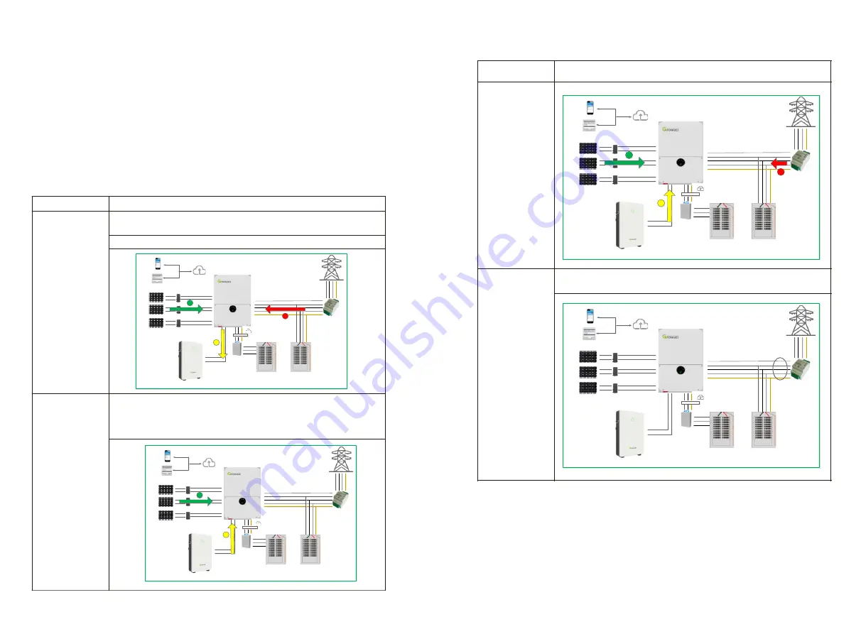
The MIN 3K-11.4K TL-XH-US system provides four energy storage modes to choose from. .

Storage Mode

Description

TOU Battery 

Charging

Charge battery from PV production and grid power (if needed) until 
it is full. Only then use PV production for self-consumption and grid
export

TOU Battery 

Discharging

If PV Production < Inverter Maximum Production (nameplate or 

limited power), discharge battery for self-consumption and grid 

export until the inverter reaches its power limit or max battery 

discharge power.

Maximum self-

consumption

Use PV production for self-consumption, then charge/discharge 

battery as needed to maximize self-consumption

Maximum self-

consumption

Export Limit

The power output from the system to the grid is limited at the


set


value

5.2 Energy Management System setting

For the photovoltaic energy storage system, several functions of the system need to set 

after the first installation and power-up.

11

Shine Phone

Shine Server

PV Panel

PV Panel

PV Panel

Cloud Server

Inverter

HV Battery

Grid

Power Meter

Backup load Panel

Home load Panel

PV1+

Bus+

Bus-

Bat+

Bat-

L1

L2

N

PE

L1

L2

L1

L2

N

RS485

PV1-

PV2+

PV2-

PV3+

PV3-

L2

N

PE

L1

PE

1

2

3

Shine Phone

Shine Server

PV Panel

PV Panel

PV Panel

Cloud Server

Inverter

HV Battery

Grid

Power Meter

Backup load Panel

Home load Panel

PV1+

Bus+

Bus-

Bat+

Bat-

L1

L2

N

PE

L1

L2

L1

L2

N

RS485

PV1-

PV2+

PV2-

PV3+

PV3-

L2

N

PE

L1

PE

1

2

Shine Phone

Shine Server

PV Panel

PV Panel

PV Panel

Cloud Server

Inverter

HV Battery

Grid

Power Meter

Backup load Panel

Home load Panel

PV1+

Bus+

Bus-

Bat+

Bat-

L1

L2

N

PE

L1

L2

L1

L2

N

RS485

PV1-

PV2+

PV2-

PV3+

PV3-

L2

N

PE

L1

PE

1

3

2

Shine Phone

Shine Server

PV Panel

PV Panel

PV Panel

Cloud Server

Inverter

HV Battery

Grid

Power Meter

Backup load Panel

Home load Panel

PV1+

Bus+

Bus-

Bat+

Bat-

L1

L2

N

PE

L1

L2

L1

L2

N

RS485

PV1-

PV2+

PV2-

PV3+

PV3-

L2

N

PE

L1

PE

Export Limit

Summary of Contents for MIN 3 K-11.4K TL-XH-US

Page 1: ...00 Download Manual Growatt New Energy Growatt USA Inc 9227 Reseda Blvd 435 Northridge CA 91324 USA 1 866 686 0298 www growatt america com T E usaservice ginverter com W MIN 3K 11 4K TL XH US Commissi...

Page 2: ...rk 3 Grid Code Mapping Table 4 Wi Fi Network Configuration 5 Energy Management System 5 1 Management System Mode Introduction 5 2 Energy Management System setting 6 Battery Life Maintenance 7 Troubles...

Page 3: ...Note Inverter MIN 3K 11 4KTL XH US Energy conversion ARO Battery ARO 6 6 9 9L C1 US Energy storage UP TO 4 ATS ATS 5K 11 4KT US EPS switching Smart meter SM US 200 Energy management Button RSD Button...

Page 4: ...at also match the L1 to the inverter Make sure the CT of L2 matched L2 input of the Service Panel that also match the L1 to the inverter c Meter Wiring When connecting the meter to the inverter refer...

Page 5: ...onnect the inverter with built in WIFI at close range We can view the inverter system information and system fouction settings with it 2 3 Connecting to Local Wi Fi Network The steps for using APP are...

Page 6: ...nsuccessful and you will need to reconnect the build in WIFI of the inverter by turning off Wifi setting in the phone and turn on again OR power cycle the system Also keep the mobile phone within 3 me...

Page 7: ...low voltage power grid 7 PRC Quebec 208 Canada Quebec low voltage power grid 8 PRC Quebec 240 Canada Quebec low voltage power grid 9 RULE21 208 US California low voltage power grid 10 RULE21 240 US Ca...

Page 8: ...e power Maximum self consumption Use PV production for self consumption then charge discharge battery as needed to maximize self consumption Maximum self consumption Export Limit The power output from...

Page 9: ...he AC charging is used to set whether to allow charging the battery from the Grid Factory Default is Disabled 1 Tap in Charge and Discharge Management 2 Find Enable AC Charging 3 Tap in ON OFF button...

Page 10: ...the time period 7 If you need to set more quarter or time periods you need to operate step 4 5 6 multiple times You can also set the energy storage mode for special days if necessary 16 16 5 2 3 EMS M...

Page 11: ...formation on the main interface if there are exist after installation The fault and alarm code on the ShineServer Page will be the same in the APP If you find a fault or alarm please click it and then...

Page 12: ...frequency 1 Restart inverter 2 If error message still exists contact manufacturer Warning 217 BDC Abnormal ARO battery error 1 Check ARO battery terminals 2 Check the connection between the inverter...

Page 13: ...just created enter the power plant page and then add a data logger The SN number of the collector is on the barcode on the side of the inverter starting with VC A power plant can contain multiple data...

Page 14: ...on the home screen Fig 9 2 Icon of APP 9 2 APP Introduction Shinephone can remotely monitor the inverter system information which has the same function as shineserver and the two information are share...

Page 15: ...ge display the list of plants under the plant account 8 tap in to add the Plant 25 Growatt USA Inc 9227 Reseda Blvd 435 Northridge CA 91324 USA 1 866 686 0298 www growatt america com T E usaservice gi...

Reviews: