Danger of damage to electronic components due to electrostatic
discharge.
Take appropriate ESD precautions when replacing and installing the
inverter.
Before connecting the power cables, you must connect both ground
wire of DC and AC side in wire box first.
DANGER
DANGER
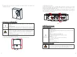
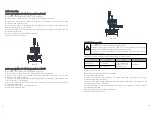
Connecting the second protective conductor
If the installation requires, the earth terminal can be used to connect a second
protective conductor or as equipment bonding. This prevents touch current if the
original protective conductor fails.
Fig 6.1
Electrical
installations
All electrical installations must be done in accordance with all local
electrical codes and the NATIOAL Electrical Code®, ANSI/NFPA 70. For
installation in Canada the installations must be done in accordance
with applicable Canadian standards. Before connecting the inverter to
the power distribution grid, contact your local electric utility company.
This connection may be made only by electrically qualified persons.
Tools for electrical installation
•
Hexagonal driver 3mm for securing the front cover and AC
connector.
•
Flat screwdriver 3mm for releasing spring terminals.
•
Cable and wire strippers.
•
Side cutters.
•
Crimping tool and cable lugs.
•
Cable marking equipment.
•
Digital multi-meter (insulation tester) with DC and AC sensitive
current clamp, voltage measurement (max. 1000 VDC) and continuity
testing functions.
INFORMATION
INFORMATION
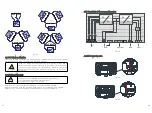
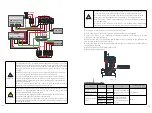
The unit converts the DC (Direct Current) generated by the photovoltaic (PV) modules to
grid-compliant AC (Alternating Current) and feed-in into the electricity grid. Growatt
inverters are built according to all required safety rules. Nevertheless, improper use may
cause lethal hazards for the operator or third parties, or may result in damage to the units
and other property.
This unit or system is provided with fixed trip limits and shall not be aggregated above 30
kW on a single Point of Common Connection.
PV Panel: Provide DC power to inverter. If using MIN TL-XH-US series PV inverter With
Arc fault current detection function, we recommend consumer connect the Tracker A and
Tracker B to different PV module strings.
Converts DC (Direct Current) power from PV panel to AC (Alternating Current) power.
Because Inverter is grid-connected, it controls the current amplitude according to the PV
module power supply. Inverter always tries to convert the maximum power from your PV
module.
Connection system: This ‘interface’ between Utility and PV inverter may consist of
electrical breaker, fuse and connecting terminals. To comply with local safety standards
and codes, the connection system should be designed and implemented by a qualified
technician.
Utility: Referred to as ‘grid’ in this manual, is the way your electric power company
provides power to your place.
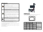
6.2.1 AC circuit breaker requirements
6.2 Intended use
6.2.2 Supported Grid Type
We suggest you to choose the AC breaker rating by below table:
MIN 3000 TL-XH-US
15A/240V
MIN 3800 TL-XH-US
20A/240V
MIN 5000 TL-XH-US
25A/240V
MIN 6000 TL-XH-US
30A/240V
MIN 7600 TL-XH-US
40A/240V
You must install a separate single-phase circuit-breaker or other load
disconnection unit for each inverter in order to ensure that the inverter
can be safely disconnected under load.
NOTE:
The inverter has the function of detecting residual current and
protecting the inverter against residual current. If your inverter has to
equip an AC breaker which has the function of detecting residual
current ,you must choose a AC breaker with the rating residual current
more than 300mA.
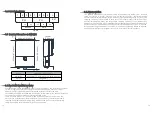
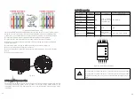
The MIN TL-XH-US series inverters are grid-tied to the public utility, the inverters is
software configurable via the user display panel for various 208Vac or 240Vac 60Hz
public utility. The following figures illustrate grids that are supported by the series
inverters. Ground connection is required for all grids. Check the grid (AC utility)
configuration type, you can use the tool to select the grid model to make the inverter
suited for the local grid type in the inverter first time starting.
21
22
WARNING


