L1
N
L2
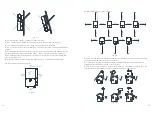
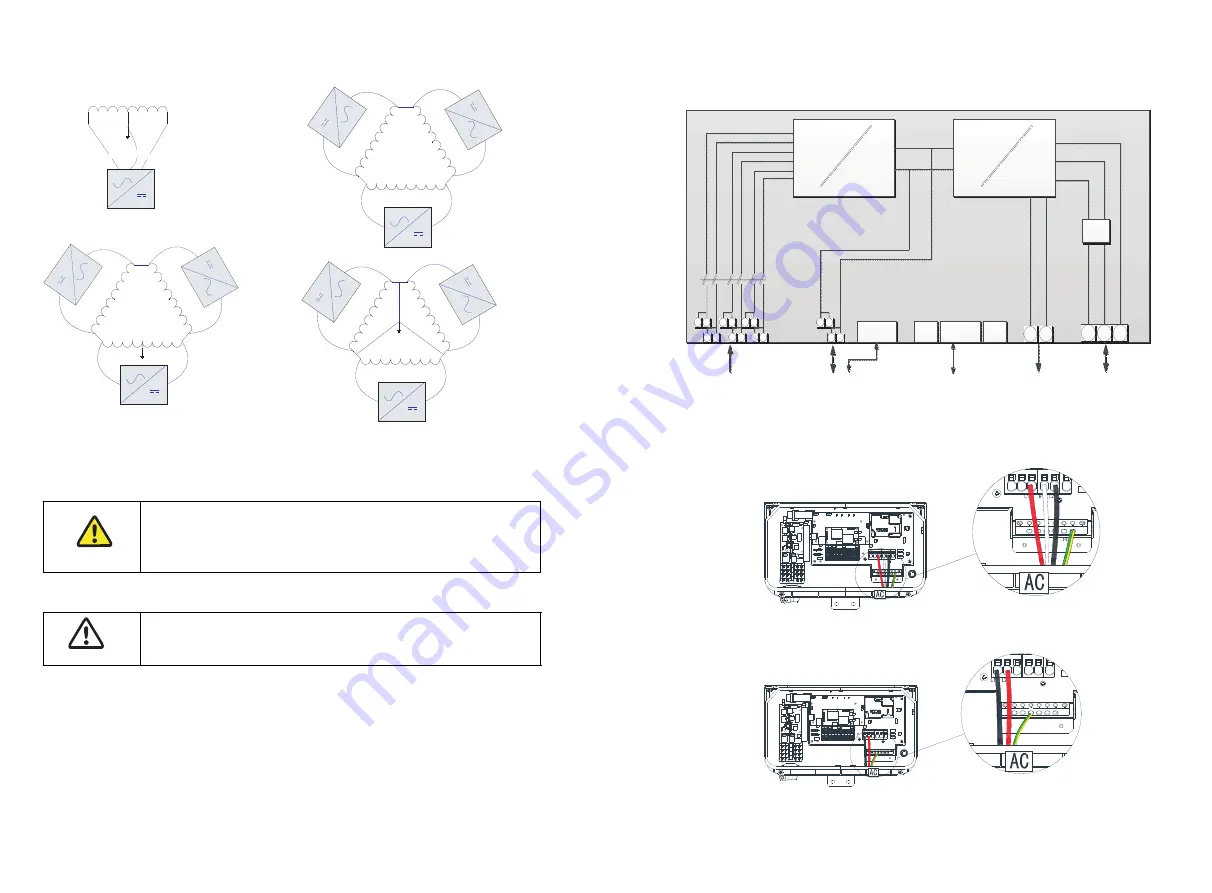
240/120 split phase
24
0V
24
0V
240V
20
8V
20
8V
208V
24
0V
24
0V
240V
240 delta
240 delta
208 delta/120WYE
There are a large number of PV module string combinations that will offer optimal
performance from either the MIN TL-XH US series inverters.
Fig 6.2
6.2.3 PV string consideration
6.2.4 Cable requirements
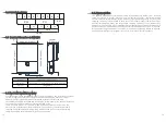
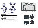
6.3 Overview of the connection area
6.3.1 AC connection area
Follow the temperature multiplication factors given in NEC 690.7
table and the PV module manufacturer specified V/Temp coefficient
to ensure PV string voltage is less than 600 Vdc. Maximum inverter PV
input voltage for all possible weather conditions in the location of
installation.
Use only solid or stranded wire but not fine stranded wire.
Use cables with high ambient temperatures.
Use cables with a large cross-section.
WARNING
NOTICE
8AWG for PV, is the The maximum allowed wire size for PV cable is 8AWG.
8AWG for Battery, is the The maximum allowed wire size for battery cable is 8AWG.
4AWG for AC, is the The maximum allowed wire size for AC able is 4AWG.
DC
DC
DC
AC
BAT+
BAT-
CAN/RS485
RS485
RGM
L1
L2
N
Local
WiFi
1
+
1-
2
+
3
+
2-
3-
PV
Battery
Communication
Back up
AC Grid
L1
L2
WiFi/4G(opt)
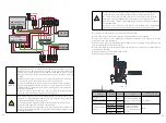
Fig 6.3
Fig 6.4
Fig 6.5
23
24


