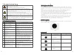
The output wiring terminals of PV modules or any other connected
MLPE device may have hazardous voltages. Touching the terminals may
cause electric shock. Before connecting PV input power cables, ensure
that the DC switch is OFF and that the DC input terminals have no
voltage.
When the inverter is running, don`t connect or disconnect PV string
or PV module in a PV string, due to the risk of electric shock.
To ensure maximum protection against hazardous contact voltages
while assembling photovoltaic installations, both the positive and the
negative leads must be strictly isolated electrically from the protective
ground potential (PE).
Risk of electric shock and fire. Use only with PV modules with a
maximum system voltage of rating of 600V or Higher.
Improper operation during the wiring process can cause fatal injury to
operator or unrecoverable damage to the inverter. Only qualified
personnel can perform the wiring work.
The positive and negative cables of PV strings are connected to PV
po) and negative(-) terminals respectively.
Since the inverter is transformer-less, the PV string connected to the
inverter cannot be grounded, ensure that the PV module output is well
insulated to ground
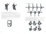
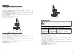
Strip 0.59 inches (15mm) of the battery cable insulation.
Insert the conduit into the left side DC-side drill guide that was opened.
Insert the 0.6*3.5 mm standard flat-blade screwdriver and press the release
mechanism and open the clamp.
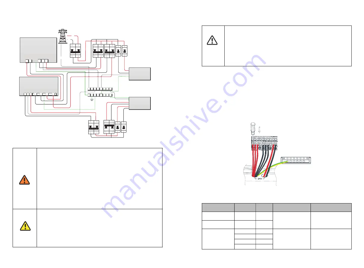
Connect the cable to the appropriate terminal blocks according to the labels on the
terminal blocks(PV+1/2/3/4,PV-1/2/3/4).
Insert the cable into the round opening and remove the screwdriver, then the cable is
automatically clamped.
Connect the PE to the Grounding terminal.
Keep the wiring box clean.
DANGER
WARNING
NOTICE
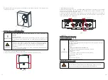
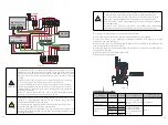
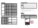
6.7 Battery connection
Fig 6.14
Fig 6.15
Cable
Battery
Inverter
Type
Conductor cross-
sectional area range
Negative line of
the power cable
-
BAT-
solid or stranded wire
but not fine stranded
wire
12-8 AWG
Positive line of the
power cable
+
BAT+
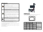
Communications
cable
EN-GND
Enable-
CAT5/6 standard
cables have eight
wires (four twisted
pairs)
N/A
ENABLE-H
RS485_H
485A
RS485_L
485B
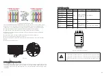
MIN XH-US Inverter
L1
L2
N
Back up
L1
L2
ATS-US
L1
L2
L1
L2
N
L1
L2
L1
L2
N
Home Load
Backup Load
Power Grid
AC Grid
Output
Input
AC Panel
Sub AC Panel
Neutral
bus-bar
Ground bar
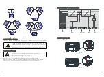
You can connect systems with multiple PV strings in parallel to the PV
input terminals, each MPPT tracker have two string input terminals
If more strings are required, they can be connected in parallel using
an external combiner box before connecting to the input terminals.
When connecting multiple independent strings, it is recommendeded
to run separately.
These series inverters have Max. four MPPT,4-mppt independent
operating.do not connect two string into 3mppt,it cannot work well.
29
30


