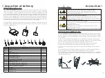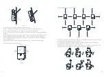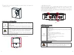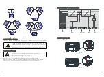
6.7.1 Power cable connection
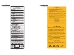
Battery short circuits may cause personal injury. The high transient
current generated by a short circuit will release a surge of energy and
may even cause fire.
To prevent the risk of electric shock, do not connect or disconnect
battery cables when the inverter is running.
Before connecting battery cables, ensure that the DC switch on the
inverter and all the switches connecting to the inverter are in the OFF
position, and the inverter contains no residual electricity. Otherwise, the
high voltage of the inverter and battery may result in electric shock.
Exposure to battery voltage can result in serious injury. Use dedicated
insulation tools to connect cables.
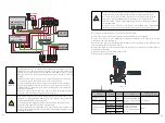
A battery switch and DC fuse can be configured between the inverter
and the battery to ensure that the inverter can be safely disconnected
from the battery. The recommended DC fuse type is littelfuse KLKD
600V/30A. Make sure the battery positive cable connecting to positive
fuse holder and positive pole of the switch in series, the battery negative
cable connecting to negative fuse holder and negative pole of the switch
in series
Make sure the battery cable is connected correctly. That is, the
positive and negative terminals of the battery connect to the positive
battery terminal and negative battery terminal on the inverter
respectively
Do not connect loads between the inverter and the battery.
Since the inverter is transformer-less, the battery connected to the
inverter cannot be grounded, ensure that the battery output is well
insulated to ground
The cable distance between the battery and the inverter should be less
than or equal to 10 meters, ideally less than 5meters
If the power cables are not installed or routed as required, the positive
or negative terminal of the battery may be short-circuited to ground ,an
AC or DC short circuit may occur and damage the inverter
Strip 15mm(
of the battery cable insulation.
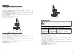
Insert the conduit into the right-side DC-side drill guide that was opened.
Insert the 0.6*3.5 mm(0.02*0.14 inch) standard flat-blade screwdriver and press the
release mechanism and open the clamp.
Connect the cable to the appropriate terminal blocks according to the labels on the
terminal blocks(BAT+,BAT-).
Insert the cable into the round opening and remove the screwdriver, then the cable is
automatically clamped.
Keep the wiring box clean.
0.59 inches)
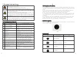
DANGER
WARNING
NOTICE
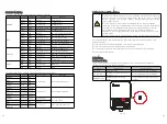
Fig 6.16
Fig 6.17
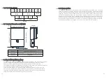
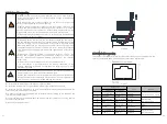
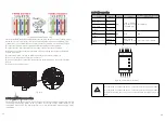
The name of the terminal for battery signal cable connection is shown below, the
terminal is standard RJ 45, and the signal cable is the CAT5/6 cable.
6.7.2 Signal cable connection
RJ45 Pin #
Wire Color
Signal
Function
T568B
T568A
1
White/Orange
White/Green
Battery wake-up signal
2
Orange
Green
Enable-
3
White/Green
White/Orange CANL
Battery CAN
communication
4
Blue
Blue
CANH
5
White/Blue
White/Blue
GND
GND
6
Green
Orange
Received
NC
7
White/Brown
White/Brown
RS485B
Battery RS485
communication
8
Brown
Brown
RS485A
31
32

