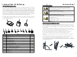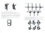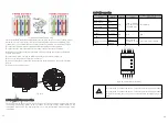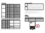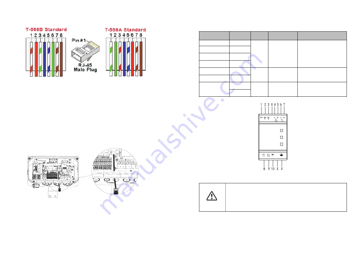
Fig 6.18 Standard cable wiring
CAT5/6 standard cables have eight wires (four twisted pairs), as shown in the diagram
below. Wire colors may differ from one cable to another. You can use either wiring
standard, as long as both sides of the cable have the same pin-out and color-coding.
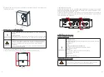
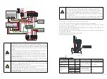
Insert the conduit into the right side COM drill guide that was opened.
Insert the CAT 5/6cable through the conduit to the inverter wiring box.
Remove the cable's external insulation using a crimping tool or cable cutter and
expose eight wires.
Insert the eight wires into an RJ45 connector, as described in Fig 6.18.
Use a crimping tool to crimp the connector.
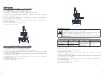
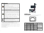
Connect the signal cable from the battery to the RJ45 port on the communication
board.
Keep the wiring box clean.
Fig 6.19
The energy meter connection is required to get information about energy flow. Before
connecting the energy meter to this product, install the energy meter. Refer to the
installation manual of the Energy Meter for more information about energy meter
installation.
6.8 Energy Meter connection
6.8.1 Cable connection
Cable
Meter
Inverter
Type
Conductor cross-sectional
area range
AC wire-L1
Φ
L1
N/A
solid or stranded
wire but not fine
stranded wire
22-18 AWG
AC wire-L2
Φ
L2
AC wire-N
N
Ground
PE symbol
CT-
Φ
L1
L1 CT +/-
N/A
N/A
N/A
CT-
Φ
L2
L2 CT +/-
Communications
cable
RS485 A+
Min. 3-wire
shielded twisted
pai
0.2- 1 mm²/ 24-18 AWG
RS485 B-
Fig 6.20 Energy Meter Terminal
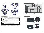
Clamp the CT connected to L1 CT around the wire connected to
Φ
L1.
Clamp the CT connected to L2 CT around the wire connected to
Φ
L2.
Ensure that the source of current transformers arrow points to the
load.
NOTICE
33
34


