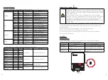
6.8.2 Energy Meter troubleshooting
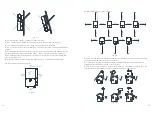
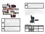
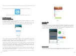
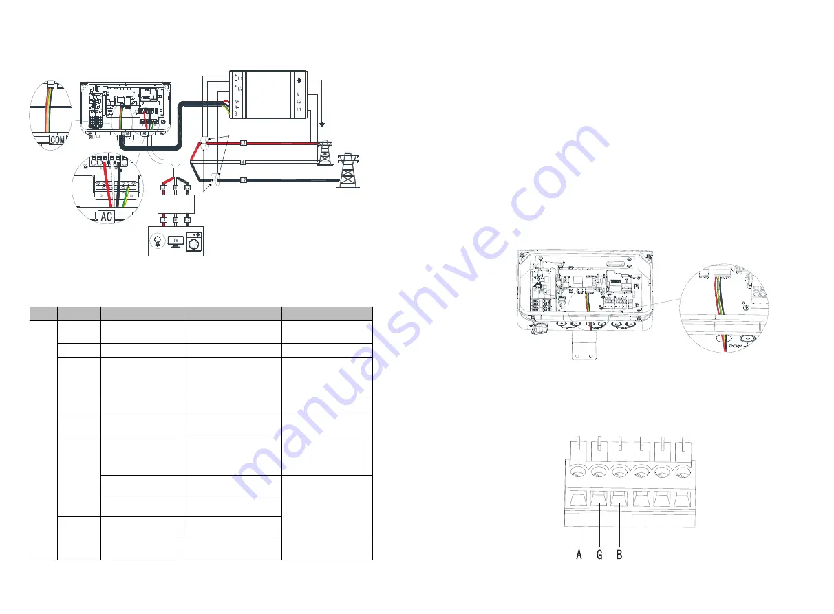
Fig 6.21 Energy Meter connection
The MIN TL-XH-US series inverters offer an Modbus RS485 communication interface, the
RS485 option enables creating a bus of connected inverters, consisting of up to 31
follower inverters and 1 leader inverter or 1 gateway or datalogger.Using this option,
inverters are connected to each other in a bus by daisy chained, via their RS485
connectors.
RS485 wiring specifications:
Cable type: Min. 3-wire shielded twisted pair (a shielded Ethernet cable (Cat5/5E STP)
may be used).
Wire cross-section area: 0.2- 1 mm²/ 24-18 AWG (a CAT5 cable may be used)
Maximum nodes: 32
Maximum distance between first and last devices: 1 km /3300 ft.
The following sections describe how to physically connect the RS485.
Insert the conduit into the right side COM drill guide that was opened.
Insert the cable through the conduit to the inverter wiring box.
Remove the cable's external insulation using a crimping tool or cable cutter and
expose wires.
Loosen the screws of the 6-pin RS485 terminal block connector.
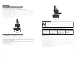
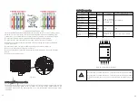
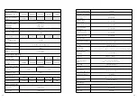
Insert the wires into the RS485A2, GND,RS485B2 pins shown below. Use four or six
wire twisted pair cable for this connection. The same color wire is used for all A2 pins, the
same color for all B2 pins and the same color for all GND pins. The wire for GND is not
necessary.
6.9 Communication connection
6.9.1 RS485 BUS communication connection
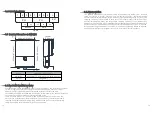
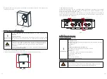
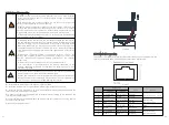
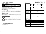
Fig 6.22 The location of RS485 BUS
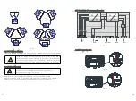
Fig 6.23 RS485 terminal block
LED
LED color
Function
Indication
Troubleshooting
RUN
Green
Flashing ON/OFF (for
1sec)
Work normally
/
Red
ON for>3sec
Internal error
Contact support
Yellow
Flashing ON/OFF (for
1sec)
No communication
Check that the
communication wires
are connected
correctly
L1/L2
Green
ON for>3sec
NO Current
/
Green
Flashing ON/OFF (for
1sec)
Positive power
/
Red
Flashing ON/OFF (for
1sec)
Negative power
Check for reversed
CTs, swapped CT
wires, or CTs not
matched with the lines
Flashing with green
LED
High voltage>130V
Check the line
voltages and the
meter rating
Flashing with yellow
LED
Low voltage<70V
Yellow
Flashing ON/OFF (for
1sec)
Break fault<30V
ON for>3sec
F r e q u e n c y i s b e l o w
45Hz or above 70Hz
Check for the
presence of high noise
35
36
Source
F
aces
Current
Transformers

