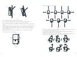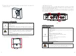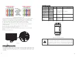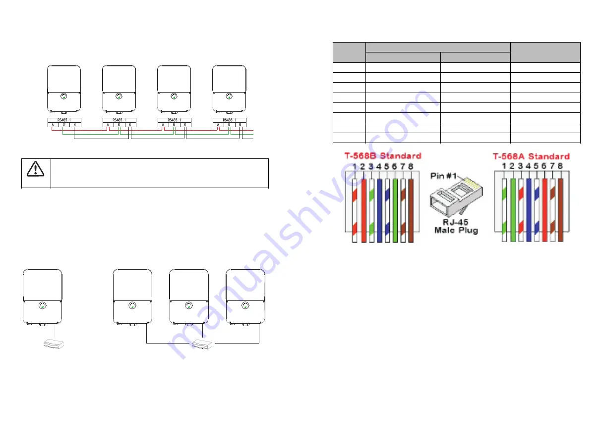
For creating an RS485 bus-connect all RS485A2, RS485B2 and GND pins in al
inverters. The following figure shown this connection:
Fig 6.24 Connecting the inverters in Daisy chain
Tighten the terminal block screws, check that the wires are fully inserted and cannot
be pulled out easily.
Push the RS485 terminal block firmly all the way into the connector on the
communication board.
Keep the wiring box clean.
Don`t Cross-connect RS485A2,B2 and GND wire.
Don`t Cross-connect RS485-1,RS485-2.
The wire for GND is not necessary.
NOTICE
6.9.2 LAN (Ethernet) communication connection (optional)
The MIN TL-XH US series inverter offer an LAN connection option to connect the inverter
to the monitoring platform. The optional wireless communication module is Wi-Fi/LAN.
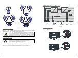
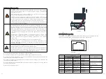
Fig 6.25
Fig 6.26
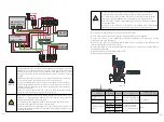
Standard cable wiring
LAN wiring specifications:
Wire type: a shielded Ethernet cable (Cat5/5E STP) may be used
Maximum distance between the inverter and the router is 100 m/ 330 ft.
RJ45 Pin #
Wire Color
10Base-T Signal
100Base-TX Signal
T568B
T568A
1
White/Orange
White/Green
T
2
Orange
Green
T
3
White/Green
White/Orange
4
Blue
Blue
Receive
5
White/Blue
White/Blue
Receive
6
Green
Orange
Receive-
7
White/Brown
White/Brown
Receive
8
Brown
Brown
Receive
CAT5/6 standard cables have eight wires (four twisted pairs), as shown in the diagram
above. Wire colors may differ from one cable to another. You can use either wiring
standard, as long as both sides of the cable have the same pin-out or color-coding.
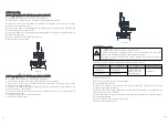
Insert the conduit into the left- side COM drill guide that was opened.
Insert the CAT 5/6cable through the conduit to the inverter wiring box.
Remove the cable's external insulation using a crimping tool or cable cutter and
expose eight wires
Insert the eight wires into an RJ45 connector, as described in Fig 6.26.
Use a crimping tool to crimp the connector.
Connect the signal cable from the router to the RJ45 port on the left-side of
communication board.
Keep the wiring box clean.
You can connect more than one inverter to the same switch/router or to different
switches/routers as needed. Each inverter sends its data independently to the Growatt
monitoring platform.
37
38

