7
Commissioning
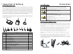
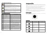
7.1 Checking Before Power-On
7.2 Powering on the system
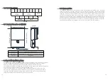
High voltages in the PV system
Risk of death or serious injury due to electric shock
Only electrically skilled persons may perform work on the PV array
Under any condition, make sure the maximum open circuit voltage of each
PV string is less than 600Vdc
Read all of these instructions, cautions, and warnings for the MIN TL-XH US
series inverter and associated PV array documentation.
Installation and commissioning must be performed by a licensed electrician
in accordance with local, state, and National Electrical Code ANSI/NFPA 70
requirements
Disconnect in the “OFF” position, verify the PV input polarity once more
simply by carefully using a 600 V, DC rated digital volt meter and probing
the positive (+) and negative (-) PV array connections.
DANGER
WARNING
CAUTION
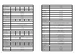
No.
Check Item
Acceptance Criteria
1 Inverter installation
The inverter is installed correctly, securely, and
reliably
2 Antenna installation
The antenna is installed correctly, securely, and
reliably.
3 Cable layout
Cables are routed properly as required by the
customer.
4 Cable tie
Cable ties are secured evenly, with no sharp
protrusions.
5 Grounding
The ground cable is connected correctly, securely,
and reliably.
6 Switches
The DC switch and all the switches connecting to
the MIN TL-XH US are in the OFF position
7 Cable connections
The AC output power cable, DC input power
cable, battery cable, and signal cable are
connected correctly, securely, and reliably.
8 Unused terminals and ports
Unused terminals and ports are fitted with
waterproofing bolts or watertight caps.
9 Cable routing pipe sealing
All cable routing pipes at the bottom of the
enclosure are sealed.
10
Cleanliness in the maintenance
compartment
The maintenance compartment interior is clean
and tidy
11 Installation environment
An appropriate installation space has been
chosen, and the installation environment is clean
and tidy.
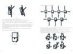
Before turning on the AC switch between the power grid with MIN TL-XH US inverter,
check that the AC voltage on the power grid side of the AC switch is within the specified
range.
Turn on the AC switch/breaker between the power grid with MIN TL-XH US inverter.
(Optional)if there is an optional breaker on the PV side, turn on the breaker.
Turn on the DC switch at the bottoms of the MIN TL-XH US inverter.
If the battery terminal connects to the batteries, turn on the battery power switch and
then the battery switch. Also if there is an optional breaker on the battery side, turn on
the breaker.
Perform quick setting and set the MIN TL-XH US inverter parameters on the local tool
function of Shinephone APP. for details, see the Operations on the Shinephone APP.
Observe the LEDs to check the MIN TL-XH US operating status.
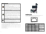
7.3 LED description
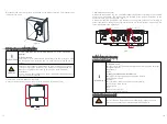
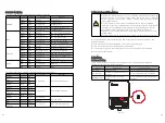
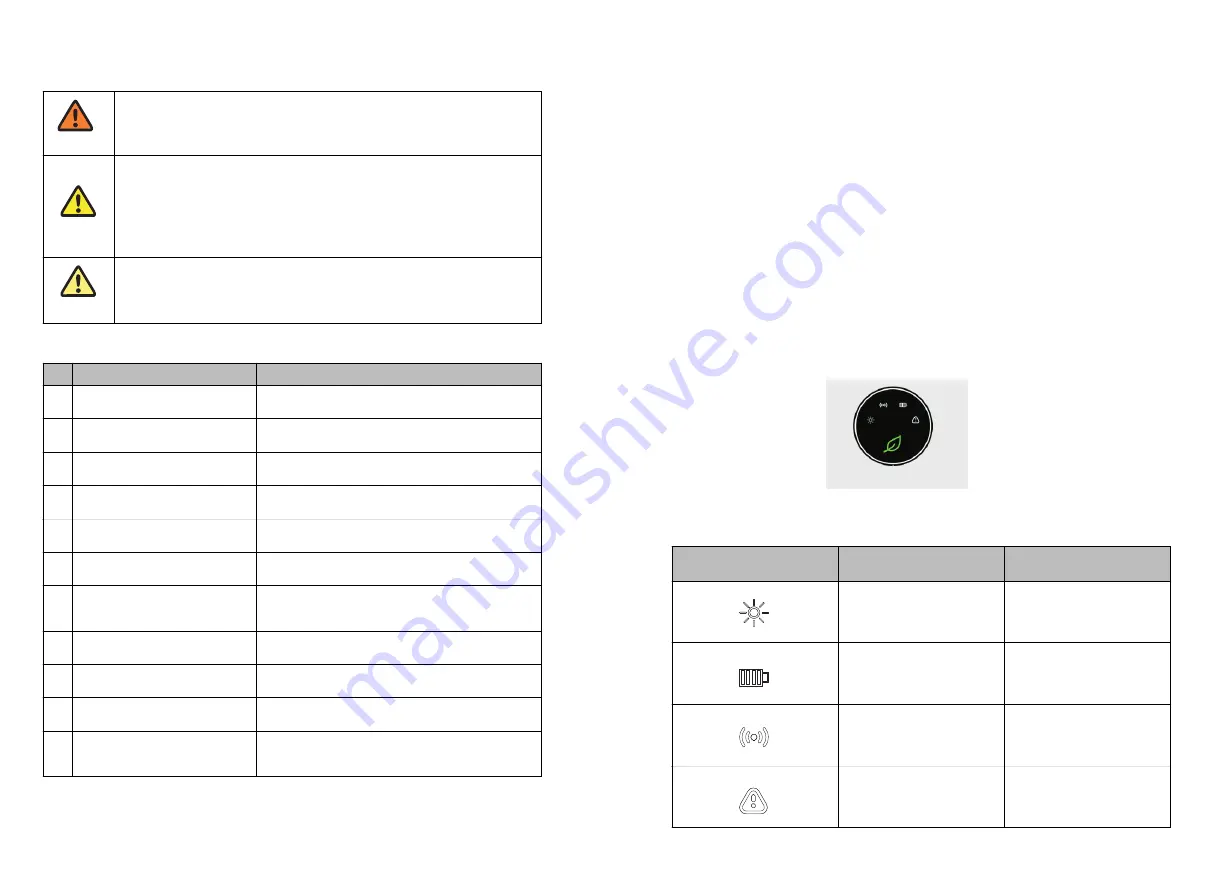
There are four LEDs in the cover of wiring box, from left to right, it is used for indicating
status of POWER, COMM, BAT. and FAULT.
Fig 7.1
7.3.1 LED Status
Label
Designation
Color
Power(POWER)
Green
Wireless
communication(COMM)
Green
Battery(BAT)
Green
Fault(FAULT)
Red
39
40

