1
Power on the system
1.1 Energy Management System Introduction
1
2
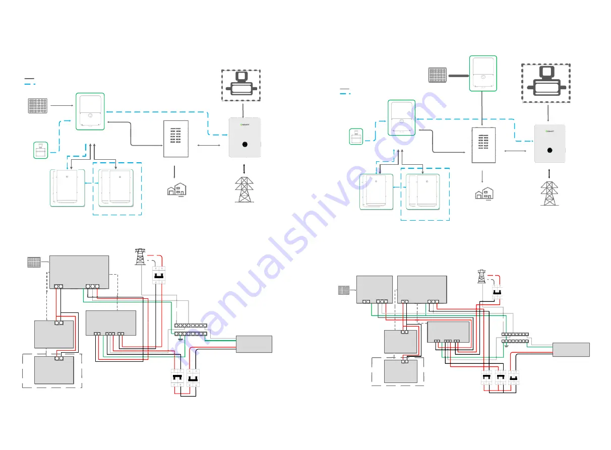
The system wiring diagram is as follows:
Fig 1.1
Fig 1.2
MIN 3K-11.4KTL-XH-US AC Couple system diagram is shown in the figure below:
Gas Generator
Emergen
cy stop
switch
AC
Main Panel
MIN 3K-11.4KTL-XH-US energy storage system diagram is shown in the figure below:
The AC Couple system wiring diagram is as follows:
Battery1
Battery2
Power Wire
Signal Wire
Whole Home
Load
SYN
200
-
XH
-
US
Grid
Fig 1.3
Fig 1.4
Gas Generator
Whole Home
Load
Main Panel
Power Wire
Signal Wire
Grid
Battery1
Battery2
Solar Inverter
PV
Emergen
cy stop
switch
AC
SYN
200
-
XH
-
US
Optional
Optional
MIN
3-11.4KTL XH-
US Inverter
MIN
3-11.4KTL XH-
US Inverter
PV
MIN XH
-US Inverter
L1
L2
N
Back up
L1
L2
AC Grid
Ground bar
L1
PV
MIN XH-US Inverter
L2
N
L1
L2
N
Whole Home Load
Power Grid
Grid
Neutral bus-bar
N
L1
AC Panel
BAT
+ -
RS485
Battery 1
RS485
Optional
RS485
BAT
+ -
Battery 2
BAT
+ -
L1
L2
L1
L2
L1 L2
Output
Input
EPS
BACKUP
SYN 200-XH-US
L1 L2
L2
Load
L1
Grid
Inverter
N
L1 L2
MIN XH
-US Inverter
L1
L2
N
Back up
L1
L2
L1
L2
L1 L2
L1 L2
AC Grid
Output
Input
EPS
BACKUP
L1
PV
MIN XH-US Inverter
L2
N
SYN 200-XH-US
L1 L2
L2
Load
L1
L2
N
Whole Home Load
Power Grid
Grid
Neutral bus- bar
Ground bar
N
L1
L1
Grid
BAT
+ -
RS485
Optional
Inverter
RS485
PV Inverter
L1
L2
N
Back up
L1
L2
Grid
Battery 1
RS485
BAT
+ -
Battery 2
BAT
+ -
N
L1 L2
AC Panel


