6.8.3 Using the Power Control Interface for EU
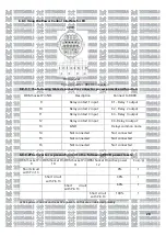
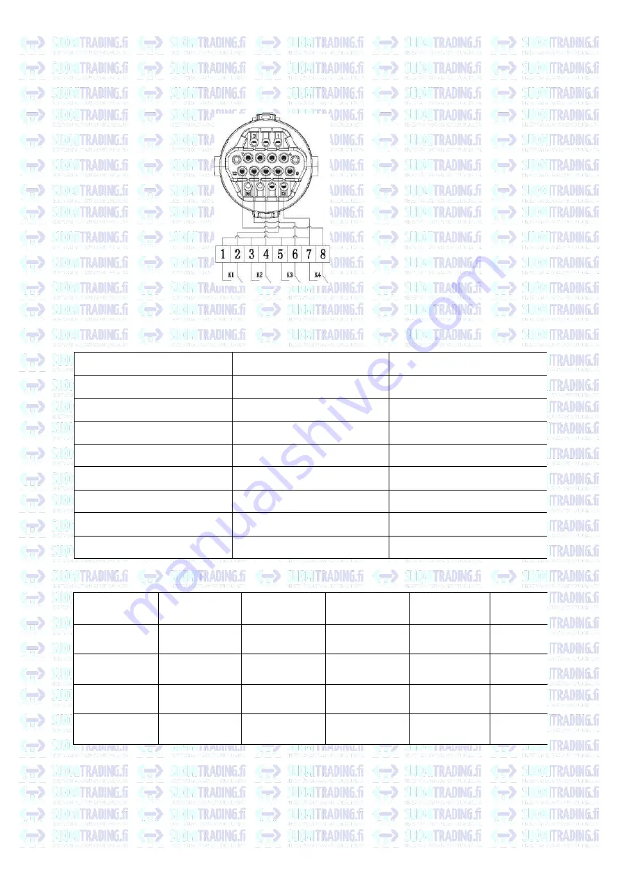
RRCR
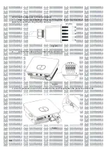
Fig 6.20 Inverter- RRCR Connection
6.8.3.1
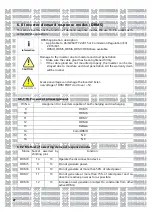
The following table describes the connector pin assignment and function:
DRM Socket Pin NO.
Description
Connect to RRCR
9
Relay contact 1 input
K1 - Relay 1 output
10
Relay contact 2 input
K2 - Relay 2 output
11
Relay contact 3 input
K3 - Relay 3 output
12
Relay contact 4 input
K4- Relay 4 output
13
GND
Relays common node
14
Not connected
Not connected
15
Not connected
Not connected
16
Not connected
Not connected
6.8.3.2The inverter is preconfigured to the following RRCR power levels:
DRM Socket Pin
9
DRM Socket Pin
10
DRM Socket Pin
11
DRM Socket Pin
12
Active power
Cos(<p)
Short circuit
with Pin 13
0%
1
Short circuit
with Pin 13
30%
1
Short
circuit
with Pin 13
60%
1
Short circuit
with Pin 13
100%
1
Active power control and reactive power control are enabled separately.
28
DRM socket
Summary of Contents for MOD 1 0KTL3-X
Page 1: ...Asennus ja k ytt ohje...
Page 19: ...Kuva 5 9 Kaaviokuva invertterin sein asennuksesta 15...
Page 60: ...Installations och bruksanvisning...
Page 78: ...Figur 5 9 Schema f r v ggmontering av v xelriktaren 15...
Page 119: ...Kontaktuppgifter 19 Suomi Trading Oy Areenakatu 7 37570 Lemp l asiakaspalvelu suomitrading fi...
Page 120: ...Installation Operation Manual...
Page 138: ...Fig 5 9 Schematic diagram of inverter wall mounting 15...
Page 179: ...Contact us 19 Suomi Trading Oy Areenakatu 7 37570 Lemp l asiakaspalvelu suomitrading fi 56...
Page 180: ......

