Debugging 7
1.
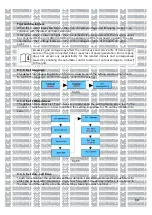
Close the DC switch on the inverter. As long as the input DC voltage is greater than
MOV,the inverter display will show the following information: No mains connection error,the in-
verter LED will turn red.
If other information is displayed, please refer to Chapter 13.If you encounter any problems dur-
ing the debugging process and cannot solve it,please contact customer service.
2.
Close the circuit breaker or switch between the inverter and the grid, the inverter will start a
countdown to the self-check,and after the self-check is normal,it will be connected to the grid.
3.In normal operation,the leaves of the inverter indicator window will turn green.
4.
Finish debugging.
30
Summary of Contents for MOD 1 0KTL3-X
Page 1: ...Asennus ja k ytt ohje...
Page 19: ...Kuva 5 9 Kaaviokuva invertterin sein asennuksesta 15...
Page 60: ...Installations och bruksanvisning...
Page 78: ...Figur 5 9 Schema f r v ggmontering av v xelriktaren 15...
Page 119: ...Kontaktuppgifter 19 Suomi Trading Oy Areenakatu 7 37570 Lemp l asiakaspalvelu suomitrading fi...
Page 120: ...Installation Operation Manual...
Page 138: ...Fig 5 9 Schematic diagram of inverter wall mounting 15...
Page 179: ...Contact us 19 Suomi Trading Oy Areenakatu 7 37570 Lemp l asiakaspalvelu suomitrading fi 56...
Page 180: ......


