21
22
Moisture and dust penetration can damage the inverter
Ø
Make sure that the waterproof cable gland is firmly tightened.
Ø
If the cable connector is not installed correctly,the inverter may be
damaged due to the penetration of moisture and dust.All warranty claims
are void.
Note
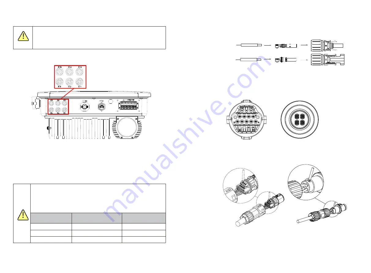
The MOD series inverter has two independent inputs, as shown in the figure below:
Fig 6.8
Note:
MOD 3-11KTL3-X (2-channel string); MOD 12-15KTL3-X and 7-11KTL3-X-AU(3-
channel string) (Optional for BAT).
The following points should be concerned when choosing photovoltaic modules:
Ø
The photovoltaic modules of each photovoltaic string are of the same specification
and model.
Ø
The photovoltaic modules of each photovoltaic string are connected in series with
the same number.
Ø
Before connecting the battery panel, please make sure that the DC input
polarity is correct, that is, the positive pole of the photovoltaic module is
connected to the DC input terminal marked "+" of the inverter, and the
negative pole is connected to the DC input terminal marked "-".
Ø
The maximum DC input current and voltage of the inverter shall not
exceed the following limits.
Model
Single maximum input
current
Maximum input voltage
MOD 3-11KTL3-X
13A/13A
1100V
MOD 7-11KTL3-X-AU
13A/26A
1100V
MOD 12-15KTL3-X
13A/26A
1100V
Note
6.4 Connect the signal cable
The MOD series inverter has an 16-Pin signal connector except Vietnam models.The
client signal line port is as follows:
1.Strip the cable 10mm through the waterproof gland, thread sleeve, and tighten the
screws.
Connect DC terminal
Cables
Cables
Positive
metal
terminal
Positive
connector
Negative
connector
Negative
metal
terminal
4~6mm²
4~6mm²
Fig 6.9
Fig 6.10
Fig 6.11
1
2
3
4
B just for Vietnam models
B just for Vietnam models
A
A


