background image

13

14

4


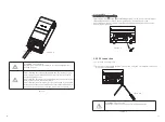
SC3500 address setting


Figure 4.1

Figure 4.2

Operation 


5.1.Power on/off

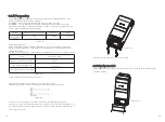
Once the unit has been properly installed and the batteries are connected well,simply
 press On/Off switch (located on the button of the case) to turn on the unit.

Figure 5.1

5.2.Operation and display panel

Figure 5.2

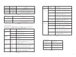
LED indicator

:

LED

LED status

Description

Add01

ON

Solar Charger 3500 slave 1

Add02

ON

Solar Charger 3500 slave 2

Add fault

ON

Solar Charger 3500 address fault 

As below showing ,the left DIP need to turn to 'PAR' when Solar Charger 3500 mix with 
Growatt SPF3000/5000.

The Solar Charger 3500 is working as slave charger of Growatt SPF3000/5000.the 

panels energy priority from high to low is : Growatt SPF3000/5000,slave 1(charger 1),

slave 2(charger 2).

The right DIP can set the charger address ,turn to “Add01”means charger 1.

“Add02”means charger 2.

WARNING: 
If you installed 2pcs Solar Charger 3500, The address DIP should be 
different ,otherwise the system would not working .

Table 4.1

Kindly reminder :for insuring the lowest consumption in the night ,we suggest 
turning off the starting up switch when system working on normal mode.

Summary of Contents for Solar Charger 3500

Page 1: ...28 Guangming Road Shiyan Street Bao an District Shenzhen P R China 86 755 2747 1942 service ginverter com www ginverter com T E W GR UM 141 A 00 Installation Manual Of Solar Charger 3500 SHENZHEN GROW...

Page 2: ...verview Safety Instructions Installation 3 1 Unpacking and Inspection 3 2 Basic installation requirements 3 3 Solar Charger connection SC 3500 address setting Table of Contents 1 2 3 4 5 1 Power on of...

Page 3: ...ng with Growatt off line Inverter SPF3000 5000 which can increase off line system charging current and satisfy high capacity battery and fast charge need Each SPF3000 5000 can match 2 pcs Solar Charge...

Page 4: ...c shock or fire 7 To reduce risk of electric shock disconnect all wirings before attempting any maintenance or cleaning Turning off the unit will not reduce this risk 8 NEVER charge a frozen battery 9...

Page 5: ...temperature humidity and air filtration 5 Battery installation option is not far below the position of energy storage machine 6 The humidity of the installation location should be 5 85 7 The ambient t...

Page 6: ...ize as below Ring terminal Figure 3 5 Note for lead acid battery the recommended charge current is 0 2C C battery capacity Please follow below steps to implement lead acid battery connection 1 Assembl...

Page 7: ...C breaker disconnector be sure positive must be connected to positive and negative must be connected to negative Figure 3 6 Table 3 2 Solar Charger 3500 has two parallel RS485 ports which can connect...

Page 8: ...ery voltage Model Max PV array open circuit voltage PV array MPPT voltage range Min battery voltage for PV charge Table 3 5 Please follow below steps to implement PV input connection 1 Remove insulati...

Page 9: ...s below showing the left DIP need to turn to PAR when Solar Charger 3500 mix with Growatt SPF3000 5000 The Solar Charger 3500 is working as slave charger of Growatt SPF3000 5000 the panels energy prio...

Page 10: ...lected as self defined Lead_Acid this program can be set up Setting range is from 50 0V to 57 4V Float charge Volt xx xV default 54V If battery type is selected as self defined Lead_Acid this program...

Page 11: ...rger MODEL Solar Charger 3500 INPUT PV Array MPPT Voltage Range 60 115VDC MAX PV Array Open Circuit Voltage 145VDC Pv1 MAX Power 1750W Pv2 MAX Power 1750W Pv1 MAX Input Current 30A PV2 MAX Input Curre...

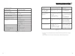
Page 12: ...after power on 1 The battery voltage is far too low 2 Battery polarity is connected reversed 1 Check if batteries and the wiring are connected well 2 Re charge battery 3 Replace battery Addr fault LE...

Page 13: ...of the following situations occurs Misuse abuse neglect or accident Alteration improper installation or application Unauthorized modification or attempted repairs Insufficient ventilation of the prod...

Reviews: