46
45
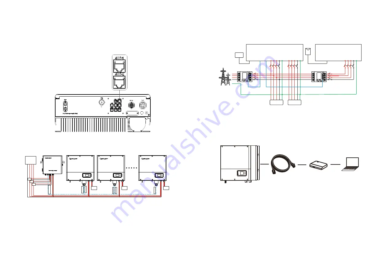
6.5.2 Use of 485-1/485-2 port
485-1/485-2 port is the extended 485 interface on SPA, which needs to be used in
conjunction with the RS485 Setting in the LCD menu to communicate with external
devices.
Chart 6.17
When set to ShineMaster mode, the wiring diagram is as follows:
Chart 6.18
The 485-1 port of the first SPA is connected to SEM-E through a network cable, and the
485-2 port is connected to the 485-1 port of the next SPA through a network cable, and
so on until the last SPA (SPA can be replaced with other inverters that support
ShineMaster function).
Note:
SPA needs to be set to Load First.
When set to Meter2 mode, the wiring diagram is as follows:
SPA
ACGRID
L3
L2
L1
L3
UPS OUTPUT
N
N
E
L3
L1
N
N
E
E
Battery
PE
Electic meter1
L2
L1
L3
L2
UPS Load
E
L1
L2
L3
N
L2
L1
Load
L1
L2
L3
N
L1
L2
L3
N
L1
L2
L3
N
METER
485-1
or
485-2
PV
Inverter
ACGRID
L3
L2
L1
N
E
Electic meter2
Chart 6.19
As the host, SPA will receive information from two meters at the same time: the first
meter (the original SPA meter) needs to be connected to the grid-side bus, and the
communication line is connected to the Meter port; the second meter needs to be
connected to the output of the inverter terminal, the communication line is connected to
485-1/485-2 port.
When set to VPP mode, the wiring diagram is as follows:
Chart 6.20
The external VPP collector is connected to 485-1/485-2 port through a network cable, at
this time SPA will respond to the relevant instructions issued by VPP.
RS485 cable
VPP collector
Computer
EPS
Load
EPS
Load
EPS
Load
Grid
C t3
Ct 2
C t1
4
8
5
|
2
4
8
5
|
1
4
8
5
|
1
4
8
5
|
2
4
8
5
|
1
R
S
4
8
5
|
1


