5
.
4
.
8
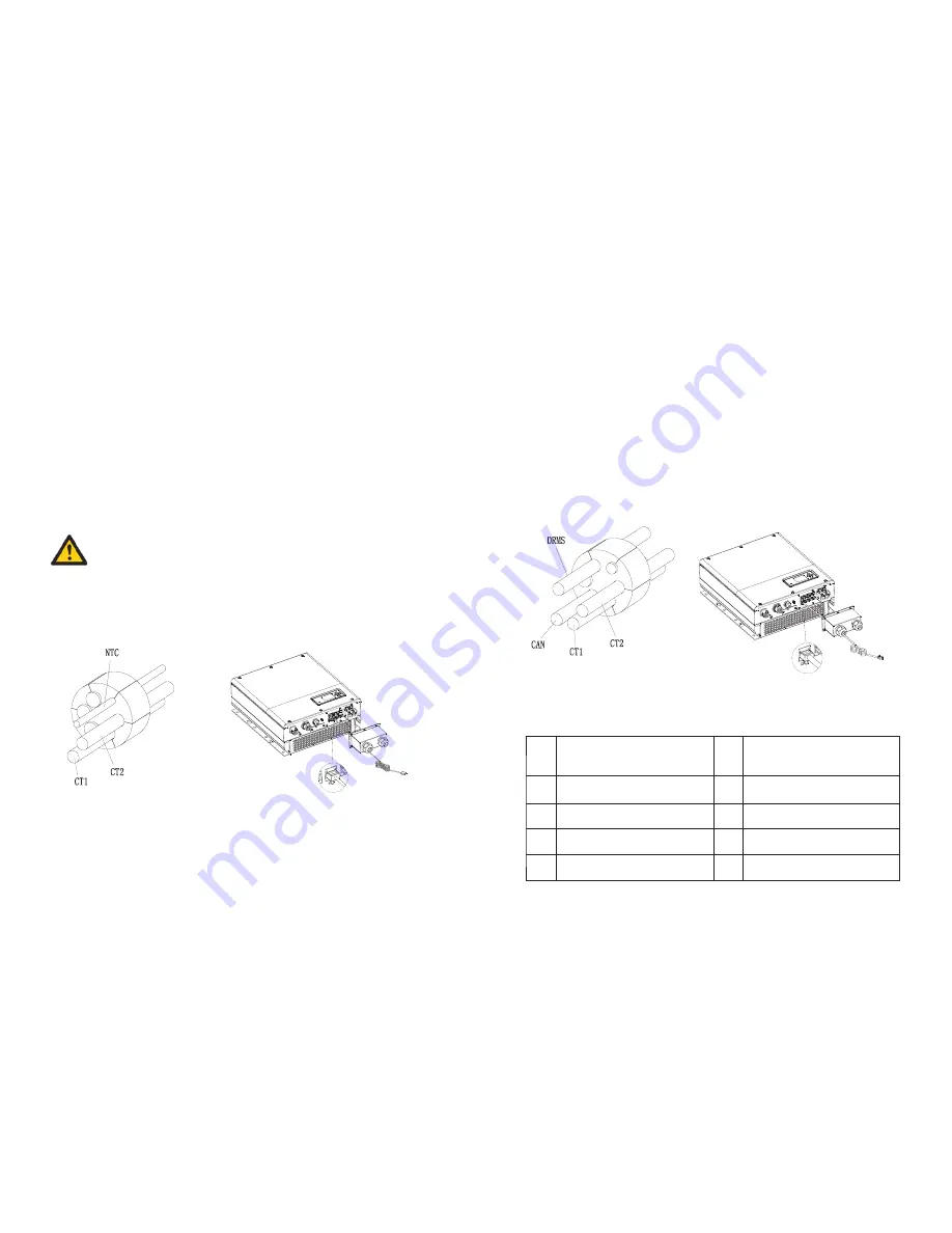
Connection of temperature probe for lead-acid battery
5
.
4
.
9
Connection of DRMs terminal(Australia only)
Fig
5.33
Fig
5.34
Fig
5.35
Fig
5.36
23
24
When customer using lead-acid battery, the temperature probe of the lead-acid battery is
used to detect the ambient temperature of the lead-acid battery, the battery temperature
cable of the SPA side connection steps are as follows:
•Unscrew the swivel nut from the cable gland.
•Thread the swivel nut over the “NTC” cable.
•Press the cable support sleeve out of the cable gland.
•Remove the filler plug from the cable support sleeve.
•Route the “NTC” cable through a min opening in the cable support sleeve.
•Thread the “NTC” cable through the cable gland.
•Insert the RJ45 plug of the network cable into the “NTC” pin connector on the inverter
until it snaps into place.
•If no other cables need to be installed, lock the waterproof cover to the SPA with
screws.
•Screw the swivel nut onto the waterproof cover.
•
probe of the temperature cable should be attached to the surrounding environment of
the lead-acid battery, and the length of this cable is 1.5m, so pay attention to the
distance of battery and SPA series.
•If the cable such as “NTC” (lead-acid battery temperature sensor) cable is not used,
please do not remove the filler plug from the cable support sleeve.
If you are using a lithium battery, you do not need to install this temperature probe, the
NOTICE:
NTC
When SPA series is applied to Australia, the DRMS terminals need to be connected, the
connection way appears as follows:
•Unscrew the swivel nut from the cable gland.
•Thread the swivel nut over the “DRMS” cable.
•Press the cable support sleeve out of the cable gland.
•Remove the filler plug from the cable support sleeve.
•Route the “DRMS” cable through an opening in the cable support sleeve.
•Thread the “DRMS” cable through the cable gland.
•Insert the RJ45 plug of the network cable into the “DRMS” pin connector on the
inverter until it snaps into place.
•If no other cables need to be installed, lock the waterproof cover to the inverter with
screws.
•Screw the swivel nut onto the waterproof cover.
DRMS
PIN
Assignment for inverter scapable
of both charging and discharging
PIN
Assignment for inverter scapable
of both charging and discharging
1
DRM1/5
2
DRM2/6
3
DRM3/7
4
DRM4/8
5
RefGen
6
COM/DRM0
7
/
8
/
RJ 45 terminal pin assignment:
Table 5.4


