background image

31

32

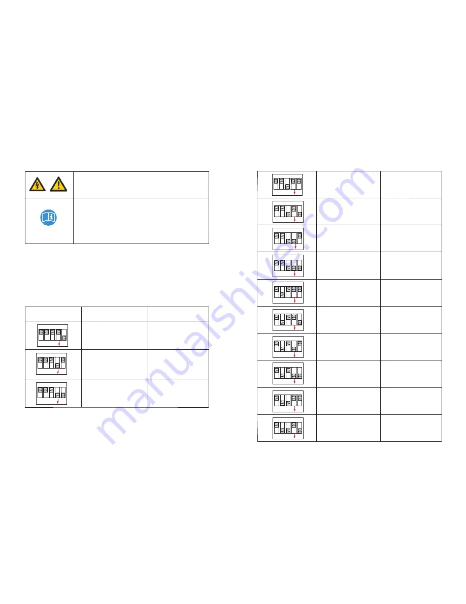
The DIP switch is composed of five-digit binary number PINS. The different combination 
of the five PINS can represent different model, which is corresponding to the local grid 
standard.  Each  small  white  PIN  has  two  statuses,  when  set  upward  to  “ON”,  its  value 
turns  to  “1”,  when  set  downward,  its  value  turns  to  “0”.  Concerning  the  matching  of 
the PIN status and the country safety standard, please refer to the table below:

Caution :

When you setting the DIP, you must turn off  AC and battery 

breaker to make sure all of the power are off.

Caution: 

1. After setting the DIP, please power on the SPA series and 

check the model display (show as 6.3.1). If the model display is 

match what you want, it means your setting is successful.

2. You need to calibrate the time that the machine is showing 

after SPA series starts up.

If the country is set incorrectly, please shut down the 

SPA series and set again

DIP switch status

Country/region / regulations

Model display

VDE 0126

GT0XXXXXX1

Queensland

GT0XXXXXX2

As4777

GT0XXXXXX3

4

2

3

1

ON

5

4

2

3

1

ON

5

4

2

3

1

ON

5

CEI 0-21

GT0XXXXXX4

G59

GT0XXXXXX5

XINA1

GT0XXXXXX6

VDE-AR-N 4105

GT0XXXXXX7

G83

GT0XXXXXX8

Norway-EN50438

GT0XXXXXX9

CQC

GT0XXXXXXA

Danmark-EN50438-1

GT0XXXXXXB

Hungary

GT0XXXXXXC

Belgium

GT0XXXXXXD

4

2

3

1

ON

5

4

2

3

1

ON

5

4

2

3

1

ON

5

4

2

3

1

ON

5

4

2

3

1

ON

5

4

2

3

1

ON

5

4

2

3

1

ON

5

4

2

3

1

ON

5

4

2

3

1

ON

5

4

2

3

1

ON

5

6.3.1 Switch to country table

Summary of Contents for SPA 1000TL BL

Page 1: ...52 A 00 SHENZHENGROWATTNEWENERGYTECHNOLOGYCO LTD No 28GuangmingRoad ShiyanStreet Bao anDistrict Shenzhen P R China T 86 755 27471942 E service ginverter com W www ginverter com Installation Operation...

Page 2: ...w 2 2 Symbols Explanation 3 1 Function 3 2 Models 3 3 Apperance 3 4 Dimensions 3 5 Nameplate 3 6 Storage 3 Product Introduction 4 Unpacking 5 Installation 5 1 Basic Installation Requirem ents 5 2 Tool...

Page 3: ...nverter 12 4 Disposing of the SPA Inverter 13 1 SPA Series Energy Storage Machine Product Specification 13 2 Torque 13 3 Appendix 6 Commissioning 12 Decommissioning 7 Start up and Shut Down SPA System...

Page 4: ...t must be operated by a trained professional electrical technician and adhere to this manual Be sure to disconnect the battery and Grid for at least 5 minutes before operation to avoid danger Please p...

Page 5: ...cable CE guidelines 4 3 Product Introduction 3 3 1 Function 3 2 Models 3 3 Apperance SPA series are the AC Coupled inverter which can store energy into battery with or without existing grid tied inver...

Page 6: ...ies 474 428 178 590 17 Nameplate contains the following information Take SPA3000 as an example Table 3 1 Table 3 2 Fig 3 2 Fig 3 3 place The stored temperature range is 25 C 60 C storage humidity rang...

Page 7: ...ze of the SPA series Do not install the inverter on a building constructed of flammable or non heat resistant materials SPA series s degree of protection is IP65 and can be installed indoors or outdoo...

Page 8: ...es on the wall Fig 5 4 Fig 5 5 Fig 5 6 Table 5 1 LAN line RJ45 sequence as follow PIN 1 2 3 4 Color White orange Orange White green Blue PIN 5 6 7 8 Color White blue Green White brown Brown LAN line 1...

Page 9: ...top edge of paper board is level As the chart 5 8a below Mark four points at the wall via the hole of the paper board then remove the paper board Drill four 8 holes at the mark point the depth is not...

Page 10: ...in sequence insert cables into connection terminal according to polarities indicates on it and tighten the screws Table 5 3 Fig 5 10 Fig 5 11 Fig 5 12 Step 3 Push threaded sleeve on to connection term...

Page 11: ...connect with AC grid and EPS OUTPUT like the chart show AC grid terminal and EPS terminal can t directly connect together EPS terminal can t connect to grid If you want to use on gird and off grid you...

Page 12: ...the cable such as CT2 cable is not used please do not remove the filler plug from Fig 5 21 During the actual operation please pay attention to the installation of current transformer as the diagram sh...

Page 13: ...to the direction of the current in live wire from grid to the load Current transformer needs to be placed in the power distribution cabinet 5 4 5 Connection of meter terminal We also can use meter in...

Page 14: ...ttery manual If the cable such as RS485 cable or CAN cable is not used please do not remove the filler plug from the cable support sleeve If you are using a lead acid battery you do not need to instal...

Page 15: ...th of this cable is 1 5m so pay attention to the distance of battery and SPA series If the cable such as NTC lead acid battery temperature sensor cable is not used please do not remove the filler plug...

Page 16: ...ate power DRM6 2 5 Do not generate at more than 50 of rated power DRM7 3 5 Do not generate at more than 75 of rated power and sink reactive power if capable DRM8 4 5 Increase power generation subject...

Page 17: ...r export to the grid With inverter energy from inverter inverter is weak the battery will discharge for load firstly and the grid will supply the power when the battery power is not enough Without inv...

Page 18: ...ase refer to 9 1 6 2 2 Fault mode 6 2 4 Checking mode 6 2 5 Standby mode 6 2 6 Shutdown mode 6 2 3 Programming mode Programming mode indicate the SPA is updating don t cut out power Grid and Battery w...

Page 19: ...the model display show as 6 3 1 If the model display is match what you want it means your setting is successful 2 You need to calibrate the time that the machine is showing after SPA series starts up...

Page 20: ...ON 5 4 2 3 1 ON 5 4 2 3 1 ON 5 4 2 3 1 ON 5 4 2 3 1 ON 5 6 4 Display and button 6 4 1 LCD display area Vb Cb 50V 40 Normal Location Description A Information B State C SPA inverter D Power flow line E...

Page 21: ...will be in stopped operational protection state The B line s information as follow In normal it will turn on page automatically when pushing the button UP the order of the paging information as follow...

Page 22: ...ou can see the setup options below after pressing Enter for 1S In the back up you can set EPS including enable or disable default is enable AC voltage default is 230V and frequency default site 50HZ U...

Page 23: ...ow Program OK and inverter will back to normal working state Then pull out the U disk and screw the waterproof lid 6 5 Communication 6 5 1 U disk Firmware upgrade USB is only used for firmware update...

Page 24: ...ion optional WiFi connection steps Remove the RS232 port cover turn the small DIP switch Pin1 and Pin2 to ON Plug WiFi S module into the RS232 port and configure the connection between WiFi module and...

Page 25: ...disconnecting battery terminals Determine if battery is inadvertently grounded If inadvertently grounded remove source from ground Contact with any part of a grounded battery can result in electrical...

Page 26: ...C V Outrange Grid voltage fault Please refer to the local grid standard for more details of the grid voltage 1 Make sure AC voltage is in the range of local standard 2 Make sure the AC cable is well c...

Page 27: ...tput voltage low 1 Check the load of EPS If overload occurred at the same time reduce EPS load 2 Restart inverter again Error message Error message Description Suggestion Error 411 I n t e r n a l c o...

Page 28: ...ibed in this document are in compliance with the above mentioned EU directives The entire EU Declaration of Conformity can be found at www ginverter com The factory warranty card is enclosed with the...

Page 29: ...s between 25 C and 60 C Do not dispose of SPA inverter together with household waste Please accordance with the disposal regulations for electronic waste which apply at the installation site at that t...

Page 30: ...y 92 0 92 5 93 0 Max Discharge efficiency 92 5 93 0 93 5 Protection Devices BAT reverse protection yes AC surge protection yes AC short circuit protection yes Ground fault monitoring yes Grid monitori...

Page 31: ...06100 Shine Wi Fi S COM interface MR00 0008600 GRRS COM interface MR00 0009601 SP CT Wireless meter sensor MR00 0006500 SPM Single phase meter Rs485 meter sensor of Eastron MR00 0008800 13 2 Torque 13...

Page 32: ...e technical problems about our products contact the Growatt Service line or dealer We need the following information in order to provide you with the necessary assistance SPA inverter Serial number SP...

Reviews: