41
42
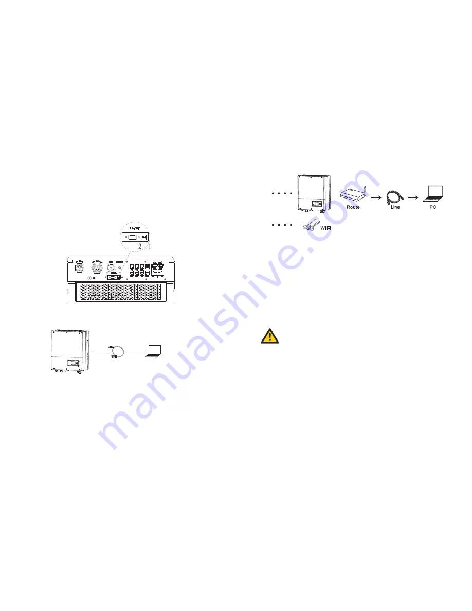
For local control, user can use USB to RS232 cable connect the inverter to computer, and
run software
ShineBus, to do parameters checking and setting, do firmware upgrade and so on.
Please contact Growatt support for ShineBus software. About ShineBus software, when
you needed,
please download from official website of Growatt.
Fig 6.20
Fig 6.21
Fig 6.22
6.5.2 Use of RS232 port
6.5.3 The SPA’
s
monitoring
The wiring diagram is as follows:
Computer
RS232-USB cable
The SPA provide RS232 interface. Users can monitor the SPA through the following
communication solution.
WiFi connection (optional)
WiFi connection steps:
•Remove the RS232 port cover, turn the small DIP switch Pin1 and Pin2 to ON.
•Plug WiFi-S module into the RS232 port, and configure the connection between WiFi
module and router.
•Create a user account online.
•Please check the ShineWiFi-S manual for details.
RF connection (optional)
RF connection steps:
•Remove the RS232 port cover, turn the small DIP switch Pin1 and Pin2 to ON.
•Plug RF module into the RS232 port, connect the Lanbox to Router.
•Create a user account online.
•Please check the ShineLink manual for details.
This kind of monitoring can only be used by the monitor of Growatt's Shineserver /shine
phone provided by the company. Through RS232 interface connect to Wi-Fi-S/shinelink,
use computer terminal/or mobile phone for data monitoring.
NOTICE:


