background image


44 

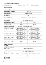
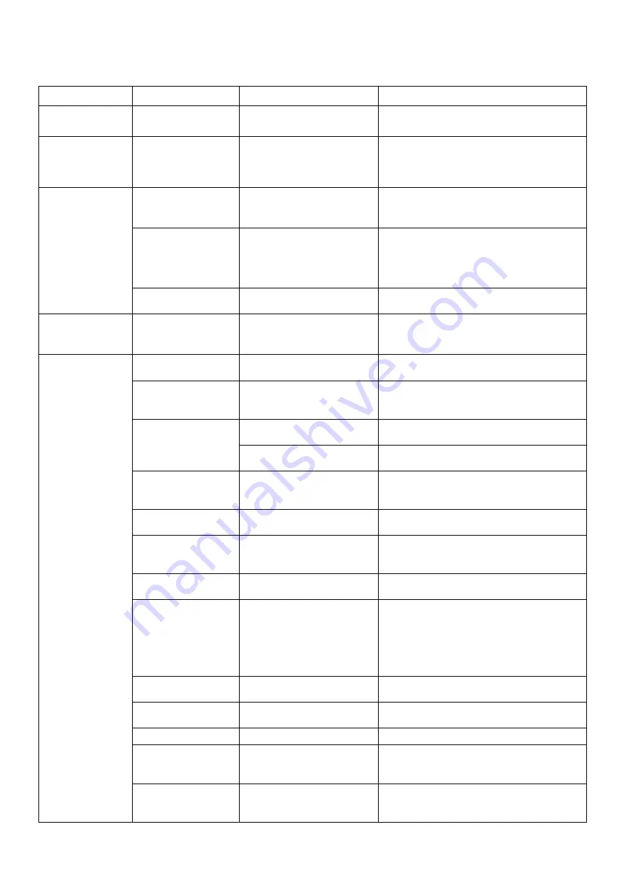
Trouble Shooting 


Problem 

LCD/LED/Buzzer 

Explanation  

What to do 

Unit shuts down 
Automatically during  

startup process. 

LCD/LEDs and buzzer will  
be active for 3 seconds  

and then  complete off. 

The battery voltage is too low . 
(<1.91V/Cell) 

1.Re-charge battery. 
2.Replace battery. 

No response after  

power on. 

No indication. 

1.The battery voltage is far too  

low. (<1.4V/Cell) 

2.Battery polarity is connected  

reversed. 

1.


Check  if  batteries  and  the  wiring  are  connected 
well. 

2.Re-charge battery. 
3.Replace battery. 

Mains exist but the  

unit works in battery  

mode. 

Input voltage is 0 on the  
LCD and green LED is  

flashing. 

Input protector is tripped. 

Check if AC breaker is tripped and AC wiring is  
connected well. 

Green LED is flashing. 

Insufficient quality of AC power. 
(Shore or Generator) 

1.


Check if AC wires are too thin and/or too long. 

2.


Check if generator (if applied) is working well or if  
input voltage range setting is correct.  
(UPS

Appliance) 

Green LED is flashing. 

Set “Battery First”  or “Solar First”  
as the priority of output source. 

Change output source priority to Utility first. 

When it’s turned on,  
internal relay is 

switching on and off  
repeatedly. 

LCD display and LEDs are  

flashing 

Battery is disconnected. 

Check if battery wires are connected well. 

Buzzer beeps  
continuously and red  

LED is on.(Fault code) 
 

Buzzer beeps once  
every second, and red 

LED is flashing. 
(Warning code) 

Fault code 01 

Fan fault. 

1.Check whether all fans are working properly. 
2.Replace the fan. 

Fault code 02 

Internal temperature of component  
is over 100

1.Check whether the air flow of the unit is blocked or  
whether the ambient temperature is too high. 
2.Check whether the thermistor plug is loose. 

Fault code 03 

Battery is over-charged. 

Restart the unit, if the error happens again, please  
return to repair center. 

The battery voltage is too high. 

Check if spec and quantity of batteries are meet  
requirements. 

Warning code 04 

The battery voltage/SOC is too low. 

1.Measure battery voltage in DC input. 
2.Check battery SOC in LCD when use Li battery. 
3.Recharge the battery. 

Fault code 05 

Output short circuited. 

Check if wiring is connected well and remove  
abnormal load. 

Fault code 06/58 

Output abnormal (Inverter voltage  
is higer than 150Vac or less than  
40Vac). 

1.Reduce the connected load. 
2. Restart the unit, if the error happens again, please  
return to repair center. 

Fault code 07 

The inverter is overload 110% and  
time is up. 

Reduce the connected load by switching off some  
equipment. 

Fault code 08 

Bus voltage is too high. 

1.If you connect to a lithum battery without 
communication, check whether the voltage points of  

the program 19 and 21 are too high for the lithum  
battery. 

2. Restart the unit, if the error happens again, please  

return to repair center. 

Fault code 09/53/57 

Internal components failed. 

Restart the unit, if the error happens again, please  
return to repair center. 

Warning code 15 

The input status is different in  
parallel system. 

Check if AC input wires of all inverters are  

connected well. 

Warning code 16 

Input phase is not correct. 

Change the input phase S and T wiring. 

Warning code 17 

The output phase not correct in  
parallel. 

1.Make sure the parallel setting are the same  
system(sigle or paralle; 3P1,3P2,3P3). 

2.Make sure all phases inverters are power on. 

Warning code 20 

Li battery can't communicate to the  
inverter. 

1.Check whether communication line is correct  
connection between inverter and battery. 
2.Check whether BMS protocol type is correct setting. 

Summary of Contents for SPF 3000TL LVM

Page 1: ...Off Grid Solar Inverter SPF 3000TL LVM Version 4 0 User Manual...

Page 2: ...gnal 11 Operation 12 Power ON OFF 12 Operation and Display Panel 12 LCD Display Icons 13 LCD Setting 15 Display Setting 20 Operating Mode Description 23 Parallel Installation Guide 25 Introduction 25...

Page 3: ...circuited Do NOT connect to the mains when DC input short circuits 4 NEVER charge a frozen battery 5 Do not disassemble the unit Take it to a qualified service center when service or repair is requir...

Page 4: ...lity grid Please consult with your system integrator for other possible system architectures depending on your requirements The WiFi GPRS module is a plug and play monitoring device to be installed on...

Page 5: ...off switch 12 Battery input 13 Parallel communication ports only for parallel model 14 Current sharing ports only for parallel model 15 AC output 16 Circuit breaker 18 RS485 communication port for ex...

Page 6: ...screws as shown below Mounting the Unit Consider the following points before selecting where to install Do not mount the inverter on flammable construction materials Mount on a solid surface Install...

Page 7: ...2 6AWG 28 6 4 33 2 SPF 3000TL LVM 48P 71A 100AH 1 4AWG 22 6 4 39 2 2 3 Nm 200AH 2 8AWG 16 6 4 33 2 Note for lead acid battery the recommended charge current is 0 2C C battery capacity Please follow b...

Page 8: ...he end of RJ45 of battery to BMS communication port RS485 or CAN of inverter 4 The other end of RJ45 insert to battery communication port RS485 or CAN Note If choosing lithium battery make sure to con...

Page 9: ...DC cut off voltage can be set up in program 19 20 and 21 User Defined 2 suitable when lithium battery without BMS communication If User Defined 2 is selected battery charge voltage and low DC cut off...

Page 10: ...municate with BMS in a parallel system you should make sure to connect the BMS communication cable between the battery and one inverter of the parallel system It s recommended to connect to the master...

Page 11: ...size as below Suggested cable requirement for AC wires Model Gauge Torque Value SPF 3000TL LVM 8 AWG 1 4 1 6 Nm Please follow below steps to implement AC input output connection 1 Before making AC in...

Page 12: ...w below steps to implement PV module connection 1 Remove insulation sleeve 10 mm for positive and negative conductors 2 Check correct polarity of connection cable from PV modules and PV input connecto...

Page 13: ...panel It could be used to deliver signal to external device when battery voltage reaches warning level Unit Status Condition Dry contact port NC C NO C Power Off Unit is off and no output is powered...

Page 14: ...ut power information 1 LCD display 2 Status indicator 3 Charging indicator 4 Fault indicator 5 Function buttons LED Indicator LED Indicator Messages Green Solid On Output is powered by utility in Line...

Page 15: ...level by 0 24 25 49 50 74 and 75 100 in battery mode and charging status in line mode These two signs indicate the charge priority SOLAR indicates solar first UTILITY indicate utility first SOLAR blin...

Page 16: ...overload Indicates the load level by 0 24 25 49 50 74 and 75 100 0 24 25 49 50 74 75 100 Mode Operation Information Indicates unit connects to the mains Indicates unit connects to the PV panel Indicat...

Page 17: ...vides power to the loads as first priority If solar energy is not sufficient to power all connected loads battery energy will supply power to the loads at the same time Utility provides power to the l...

Page 18: ...ed 2 suitable when lithium battery without BMS communication If User Defined 2 is selected battery charge voltage and low DC cut off voltage can be set up in program 19 20 and 21 It is recommended to...

Page 19: ...Fault mode charger source can be programmed as below Solar first Solar energy will charge battery as first priority Utility will charge battery only when solar energy is not available Utility first U...

Page 20: ...cted solar input power will be automatically adjusted according to the following formula Max input solar power Max battery charging power Connected load power Solar power balance disable If selected t...

Page 21: ...min Settable 46 Battery equalized timeout Default 120min 5min 900min Settable 47 Equalization interval Default 30days 1 days 90 days Settable 48 Equalization activated immediately Equalization activat...

Page 22: ...power battery voltage output voltage output frequency load percentage load in VA load in Watt DC discharging current main CPU Version and second CPU Version Setting Information LCD display Input volt...

Page 23: ...t 70 Load in VA When connected load is lower than 1kVA load in VA will present xxx VA like below chart When load is larger than 1kVA 1kVA load in VA will present x x kVA like below chart Load in Watt...

Page 24: ...22 Main CPU version checking Main CPU version 502 00 719 Secondary CPU version checking Secondary CPU version 002 00 719 Battery SOC Battery SOC 80...

Page 25: ...when connected load is pretty low or not detected No output is supplied by the unit but it still can charge batteries Charging by utility and PV energy Charging by utility Charging by PV energy No cha...

Page 26: ...y at line mode Charging by PV energy Line Mode The unit will provide output power from the mains It will also charge the battery at line mode Charging by utility Battery Mode The unit will provide out...

Page 27: ...ote If the package includes share current cable and parallel cable the inverter is default supported parallel operation You may skip section 3 If not please purchase parallel kit and install this unit...

Page 28: ...communication board Step 5 Remove two screws as below chart to take out cover of parallel communication Step 6 Install new parallel board with 2 screws tightly Step 7 Re connect 2 pin and 14 pin to o...

Page 29: ...ry to cause parallel inverters not working Recommended AC input and output cable size for each inverter Model AWG no Torque SPF 3000TL LVM 8 AWG 1 4 1 6Nm You need to connect the cables of each invert...

Page 30: ...can use 50A breaker for only 1 unit and each inverter has a breaker at its AC input Note2 Regarding three phase system you can use 4 poles breaker the rating is up to the current of the phase which ha...

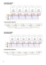
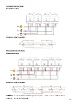
Page 31: ...29 Three inverters in parallel Power Connection Communication Connection Four inverters in parallel Power Connection Communication Connection...

Page 32: ...30 Five inverters in parallel Power Connection Communication Connection Six inverters in parallel Power Connection Communication Connection...

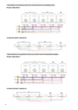
Page 33: ...Operation in Three Phase One inverter in each phase Power Connection Communication Connection Two inverters in one phase and only one inverter for the remaining phases Power Connection Communication...

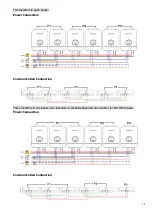
Page 34: ...two phases and only one inverter for the remaining phase Power Connection Communication Connection Three inverters in one phase and only one inverter for the remaining two phases Power Connection Comm...

Page 35: ...o inverters in each phase Power Connection Communication Connection Three inverters in one phase two inverters in second phase and one inverter for the third phase Power Connection Communication Conne...

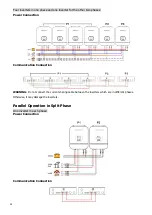
Page 36: ...Connection Communication Connection WARNING Do not connect the current sharing cable between the inverters which are in different phases Otherwise it may damage the inverters Parallel Operation in Sp...

Page 37: ...ction Communication Connection Three inverters in each phase Power Connection Communication Connection WARNING Do not connect the current sharing cable between the inverters which are in different pha...

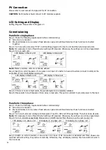
Page 38: ...warning 15 LCD display in Master unit LCD display in Slave unit Step 5 If there is no more fault alarm the parallel system is completely installed Step 6 Please switch on all breakers of Line wires i...

Page 39: ...2P0 2P1 split phase 120V 208V 2P0 2P2 split phase 120V 240V Note It s necessary to turn off switch when setting LCD program Otherwise the setting can not be programmed Step 3 Turn on all units sequent...

Page 40: ...ted by internal converter components 06 Output voltage is too high 07 Overload time out 08 Bus voltage is too high 09 Bus soft start failed 51 Over current or surge 52 Bus voltage is too low 53 Invert...

Page 41: ...Beep once every second 16 Parallel input phase error Beep once every second 17 Parallel output phase loss Beep once every second 20 BMS communication error Beep once every second 33 BMS communication...

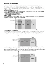
Page 42: ...float stage when the setting equalization interval battery equalization cycle is arrived or equalization is active immediately the controller will start to enter Equalize stage Equalize charging time...

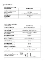
Page 43: ...PS 65Vac 5V Appliances Low Loss Return Voltage 100Vac 5V UPS 70Vac 5V Appliances High Loss Voltage 140Vac 5V High Loss Return Voltage 135Vac 5V Max AC Input Voltage 150Vac Nominal Input Frequency 50Hz...

Page 44: ...d 20 21 4Vdc 20 load 50 20 2Vdc load 50 44 0Vdc load 20 42 8Vdc 20 load 50 40 4Vdc load 50 Low DC Warning Return Voltage Lead Acid Mode 23 0Vdc load 20 22 4Vdc 20 load 50 21 2Vdc load 50 46 0Vdc load...

Page 45: ...rve Battery Voltage per cell Charging Current 2 43Vdc 2 35Vdc Voltage 2 25Vdc 100 50 T0 T1 T1 10 T0 minimum 10mins maximum 8hrs Current Time Bulk Absorption Maintenance Constant Current Constant Volta...

Page 46: ...eck whether the thermistor plug is loose Fault code 03 Battery is over charged Restart the unit if the error happens again please return to repair center The battery voltage is too high Check if spec...

Page 47: ...8 settings are the same for all parallel inverters 3 Check whether the current sharing cables are connected well in the same parallel phases 4 Check whether all neutral wires of all parallel units are...

Reviews: