15
16
Buzzer
:
Status
Description
Beeps every 3 seconds
Inverter is in warning state
Beeps constantly
Inverter is in error state
Table 6.2
Buttons:
Function Key
Description
ESC
To exit setting mode
UP
To go to previous selection
DOWN
To go to next selection
ENTER
To confirm the selection in setting mode or enter setting mode
Table 6.3
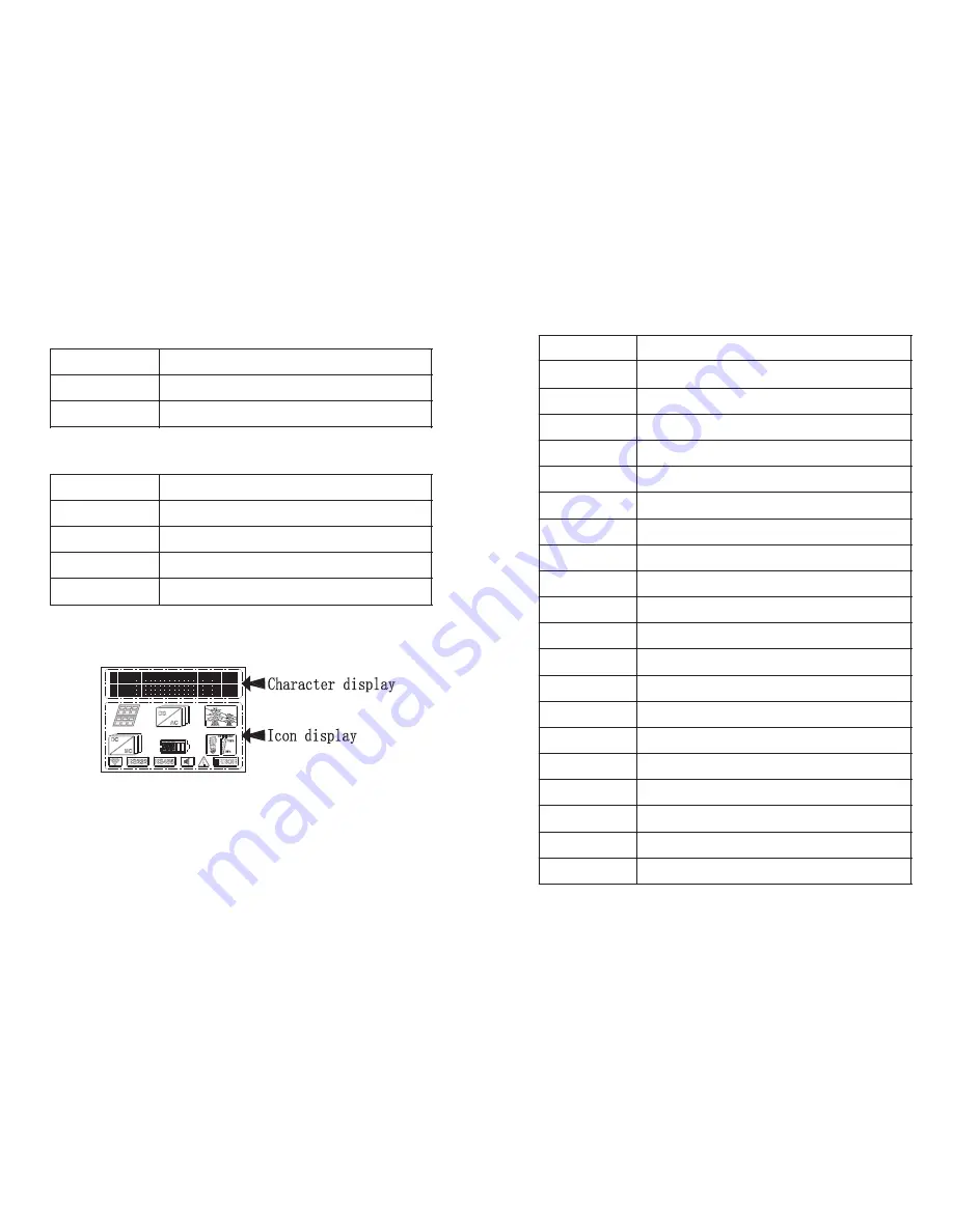
LCD display
:
Figure 6.3
1. LCD display description
In the first line of the LCD, it displays the warning error code & current status & setting
item.
The current status includes Normal, Warn, Error. More info about error & warning
code and setting item please refer to following pages
In the second line of the LCD, it displays input & output parameters and time of
inverter
Items
Description
Vb/Cb: xx.xV/ xxx%
Battery voltage/battery capacity
Vpv: xxxV/ xxxV
PV voltage:PVA voltage/PVB voltage
Ic_pv: xx.x / xx.x A
PV charge current: PVA charge current/ PVB charge current
Ppv: xxxx/ xxxxW
PV charge power: PVA charge power/ PVB charge power
AC_In: xxxV/ xxHz
Voltage/frequency of input AC
AC_Out: xxxV/ xxHz
Voltage/frequency of output AC
Ichr_ac: xx.xA
AC charge current
Ichr_all: xxx.xA
Total charge current
PL: xxxxW/ xxxxVA
Power of load
Per_Load: xxx%
Load percentage
Epv_d: xxxx.x KWh
Daily PV generation
Epv_a: xxxx.x KWh
Total PV generation
Ec_d: xxxx.x KWh
Daily charged capacity of battery
Ec_a: xxxx.x KWh
Total charged capacity of battery
Ed_d: xxxx.x KWh
Daily discharged capacity of battery
Ed_a: xxxx.x KWh
Total discharged capacity of battery
20xx/xx/xx xx:xx
Time
SerNo: xxxxxxxxxx
Series number
Model: xxxxxxxxxx
Model
FW Version: xxxx
Firmware version
Table 6.4


