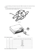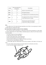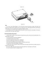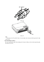
and set again.
The DIP switch is composed of six-digit binary number PINS. The different combination of the six PINS can
represent different inverter’s model, which is corresponding to the local grid standard. Each small white PIN
has two statuses, when set upward to “ON”, its value turns to “1”, when set downward, its value turns to “0”.
Concerning the matching of the PIN status and the country safety standard, please refer to the table below:
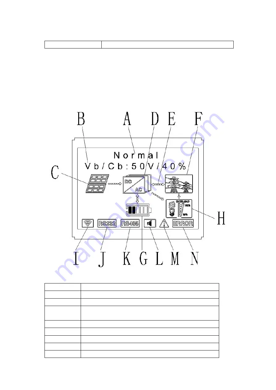
6.4 Display and button
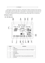
6.4.1 LCD display area
Chart 6.2
Location
Description
A
State
B
Information
C
PV input (If you connect two tracks, it will show two. Otherwise
show one)
D
SPH inverter
E
Power flow line
F
Grid
G
Battery (Show the SOC in five grid, Every grid represents 20%)
H
Local load


