background image


20 

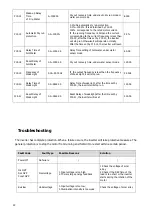
P15.14 

Wake-up Delay 
Time 

of  Dry-Water 

0~10000S 

Dry out recovery time

under auto dry run mode or 

water sensor mode 

600S 

P15.15 

Automatic Dry run 
protection 

0.0~100.0% 

0.0%:No automatic dry run protection 

0.1%~100.0%:It is determined by P15.15 
100%  corresponds to the rated motor current. 

If  the running frequency >30Hz

,

and the current 

corresponding to the current frequency is less than 

P15.15,


after the time set by P15.13,


the inverter 

will stop run

,

otherwise

,

it will operate normally.


After the time set by P15.14,


the inverter will


reset. 

0.0% 

P15.16 

Delay Time of 

Full-Water 

0.0~1000.0S 

Delay Time setting of Full-water

under water 

sensor mode 

60.0S 

P15.18 

Reset Delay of 
Full-Water 

0.0~1000.0S 

Dry out recovery time

under water sensor mode 

120.0S 

P15.19 

Frequency of 
Weak Light 

0.00~50.00Hz 

If  the output frequency is less than the frequency 

of Weak Light

it will stop run. 

5.00Hz 

P15.20 

Delay Time of 

Weak Light 

0.0~3600.0S 

Delay Time of weak light, after the time set by 

P15.20, the inverter will stop run. 

100.0S 

F15.21 

Reset Delay of 
Weak Light 

0.0~3600.0S 

Reset Delay of weak light,after the time set by 
P15.21, the inverter will reset 

300.0S 


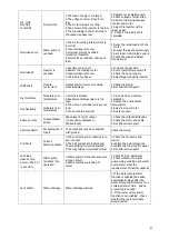
Troubleshooting 

 
The inverter has complete protection. When a failure occurs, the inverter will take protective measures. The 
general protection is to stop the motor from running and forbid it to restart within a certain period.  
 

Fault Code 

Fault type 

Possible Reasons 

Solution 

Power off 

No failure  

Inc OVP 
Dec OVP  

Const OVP 

Overvoltage 

1.


Input voltage is too high 

2.


There is large energy feedback 

1.Check the voltage of solar 

array  
2.Check if the DEC time of the 

load is too short or the inverter 
starts during the rotation of the 

motor 

Bus low 

Undervoltage 

1.Input voltage is too low; 
2.Illumination intensity is too weak 

Check the voltage of solar array 

Summary of Contents for SPI 11000

Page 1: ...Solar Pump Inverter 3000W 22000W Version 1 2 User Manual...

Page 2: ...Unpacking and Inspection 5 Mounting the Unit 5 Wiring Introduction 7 Terminal Introduction 7 Assemble DC Connector 8 Assemble AC Connector 8 Wiring of Water Level Sensor 9 Assemble Sensor connector 1...

Page 3: ...es and installations Knowledge of the applicable standards and directives Knowledge of and compliance with this document and all safety information Safety Instructions WARNING This chapter contains im...

Page 4: ...water is pumped maybe the wires on motor connection are reversely connected Please reverse any two wires of them 3 When testing water pump be sure to install water pump at appropriate water level Neve...

Page 5: ...er The inverter is suitable for submersible pumps ground pumps swimming pool pumps and other pumps using three phase asynchronous motors Features Rated power 3KW to 22KW Inbuilt MPPT solar controller...

Page 6: ...4 Product Overview 1 LCD display 2 LED indicators 3 Function buttons 4 DC switch 5 PV input 6 Water level sensor port WELL 7 Water level sensor port TANK 8 AC output 9 GPRS WIFI communication port...

Page 7: ...mable construction materials Mount on a solid metal surface Avoid direct sunlight Be sure the environment is shady and cool Be sure to install the inverter into a box with waterproofand dustproof Inst...

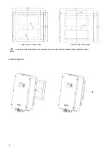
Page 8: ...6 3 3 phase 380V 7 5kw 11kw 3 phase 380v 13kw 22kw SUITABLE FOR MOUNTING ON CONCRETE OR OTHER NON COMBUSTIBLE SURFACE ONLY Install Safety Nut...

Page 9: ...of solar array AC Output M 1 Connect with motor U phase M 2 Connect with motor V phase M L Connect with motor W phase M PE Connect with protective ground wire Water Level Sensor Input Switch Value S1...

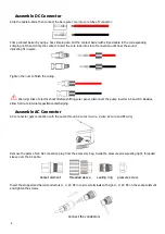
Page 10: ...ric shock Before shifting solar panel disconnect the pump inverter AC and DC Besides allow 5 minute internal capacitance discharging Assemble AC Connector AC connnector gets connection with the pump t...

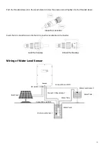
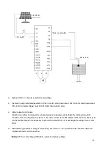
Page 11: ...the connector Insert the AC onnnection plug into the AC connection receptable on the inverter Lock the housing Unlock the housing Wiring of Water Level Sensor DC Switch Connect S2 and COM Water Tube C...

Page 12: ...level sensor 1 detects that the water level of well is lower than the level set by sensor the pump inverter will delay for 60s then turn off output protection pump The water level recovers Wait for 60...

Page 13: ...5 4 6 6 10 10 SPI 9200 21 3PH 380V 4 4 4 6 10 10 10 SPI 11000 24 3PH 380V 4 4 6 10 10 10 16 SPI 13000 28 3PH 380V 6 6 6 10 10 10 10 SPI 15000 30 3PH 380V 6 6 6 10 10 16 16 SPI 18000 39 3PH 380V 6 6 1...

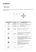
Page 14: ...ps control Confirm Programming Key 1 Press for a short time to enter programming mode After altering parameter press for a short time to confirm the alteration 2 Press for 2s to enter the programming...

Page 15: ...e LCD display information includes operation data control parameters and historical parameters The information on the display will be switched in turns by pressing UP DOWN key The selectable informati...

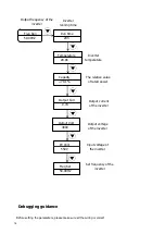
Page 16: ...0 00HZ Output frequency of the inverter Freq Set 50 00HZ Set frequency of the inverter PV Volt 550V Input voltage of the inverter Output Volt 380V Output Curr 0 7A Output current of the inverter Capac...

Page 17: ...Under the normal strong light condition if the working frequency is low or the water volume is small it indicates that the motor line may be connected reversely so it is necessary to set function cod...

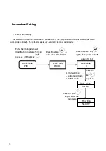
Page 18: ...terminal work mode Click the back key to enter the main page Click the key again to set OK Press the enter key again Change the default value of 1 to 0 Work mode P00 Enter the main parameter modificat...

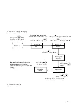
Page 19: ...ameter modification interface for long press 2s for Enter key Model set P02 01 Turn up to group P02 and click enter key to enter P02 00 Rating curr P02 05 Flip up to P02 05 Rating curr 11 3A Click ent...

Page 20: ...manual operation NOTE When set P00 and P02 paramaters first must set manual operation power off the inverter P15 not need 1 auto operation mode 2 communication operation mode 1 P00 03 MAX Output freq...

Page 21: ...02 02 P02 05 Model confirmation P02 02 Rated frequency of asynchronous motor 0 01Hz P00 03 Set this parameter according to rated frequency on the pump nameplate 50 00Hz P02 04 Rated voltage of asynchr...

Page 22: ...output frequency is less than the frequency of Weak Light it will stop run 5 00Hz P15 20 Delay Time of Weak Light 0 0 3600 0S Delay Time of weak light after the time set by P15 20 the inverter will st...

Page 23: ...3 The time of overload runing is too long 4 Control board abnormal 1 Clean air flue or improve ventilation 2 Degree the environment temperature 3 Select a proper motor 4 Ask for support Rec Overtemp...

Page 24: ...g is needed 2 If the water empty alarm function is not enabled check whether there are terminals misconnected Com Fault Communication failure Device or circuit damage Reset Get after sells support War...

Page 25: ...900 500 680 250 5500 13 0 50 60 3PH 380V 480 x 340 x 155 9 SPI 7500 900 500 680 250 7500 18 0 50 60 3PH 380V 530 x 370 x 165 11 SPI 9200 900 500 680 250 9200 21 0 50 60 3PH 380V 530 x 370 x 165 11 SP...

Reviews: