7
COLD FRAMES
Revision date: 02.12.09
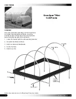
LAY OUT THE BUILDING SITE
After the site is prepared, lay out the cold frame position on
the site. Taking these steps
before
assembling the shelter
saves time and ensures that the structure is positioned as
desired.
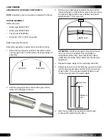
Drive ground posts to the same depth. Width of the shelter
is measured from the center of one ground post to the
center of the remaining ground post.
SQUARE THE SITE
Gather the parts:
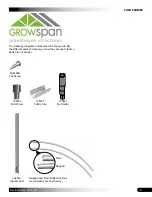
• Ground posts (#104543)
• Tek screws (#FA4482B)
1. Identify a corner where a ground post will be positioned
and drive the first ground post into the ground.
NOTE:
Insert the ground post driver (104545) into the
top of the ground post to protect the post and drive the
post into the ground.
Drive the post at least one (1) foot
into the ground.
2. After the first corner ground post is in place, string a
line the width of the building (4' center-to-center) and
drive the second ground post into the ground just
enough to hold it in place.
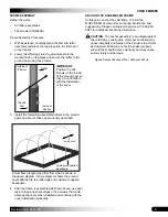
4. String a line at least as long as the building from the
first stake at 90°.
NOTE:
A transit can be used to ensure an accurate 90°
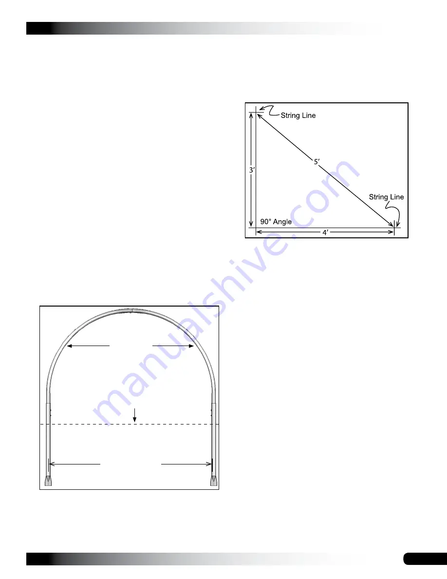
angle, or the 3-4-5 rule can be used. Refer to diagram.
Using multiples of 3-4-5 such as 6-8-10 or 12-16-20
helps to maintain an accurate 90° angle.
5. After squaring the position of the cold frame, measure
the length and drive the next corner ground post.
NOTE:
Rafter spacing is 2' on-center. Measure the
length from the center of the first ground post to the
center of the last ground post on the same side of the
shelter.
6. Repeat Step 5 for the last corner post.
NOTE:
The distance measured diagonally between
corner posts must be equal for the building to be
square.
7. Check all dimensions (and adjust if needed) before
driving the remaining posts to the required height.
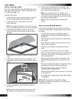
8. After all corner posts are accurately installed, tie a
string line between the tops of the corner ground posts
on the same side of the shelter. The string is used to
identify the tops of all remaining ground posts. The
string must remain tight and level.
9. Use a tape measure to mark the two (2) feet on-center
locations of the remaining ground posts.
10. Drive the remaining ground posts into the ground at
the required two (2) feet on-center width and the height
identified by the string.
NOTE:
Verify that each post is plumb and driven to the
correct depth.
11. Continue with the
Rafter Assembly
steps that follow.
Rafter Pipes
4' center-to-center
Ground Level
NOTE:
Rafter width is measured from the center of one
rafter leg to the center of the other rafter leg as shown.
3. Use a transit or line level to drive the second corner
post to the same depth as the first ground post.


