29
GROWSPAN
™
GOTHIC PREMIUM HIGH TUNNELS
Revision date: 01.08.21 108185_86_87_88_89H
INSTALL THE DROP-DOWN PANEL (continued)
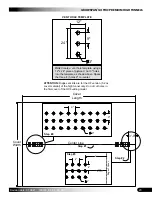
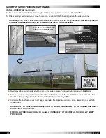
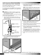
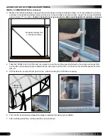
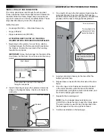
10. Carefully lift the assembly and insert the tapered/free
end of the 131S075 pipe through the 2" drive pipe hole,
or 'X', in the end panel.
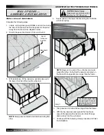
11. Align the plate mounting holes with the mounting
holes drilled in the end rafter (Step 3) and reattach the
mounting plate using two 1/4" x 4" carriage bolts, 1/4"
lock nuts, and 1/4" flat washers.
NOTE:
Cover is not shown in the above diagram.
Diagram shows gearbox mounted to the end rafter on
the outside of the end wall cover.
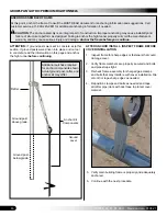
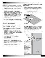
12. Move inside the frame and slide a 106734 band clamp
over the tapered end of the 131S075 pipe.
106734 Band
Clamp
Drive Pipe
Gearbox bolted
to end rafter.
2" drive
pipe hole
or 'X'
End Panel
Frame shown may differ from actual frame.
Drive Pipe
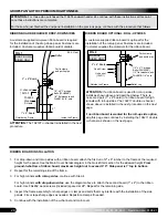
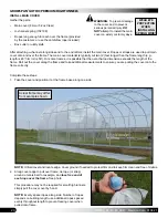
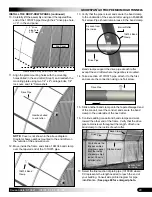
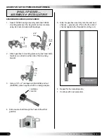
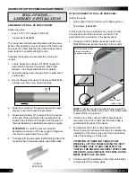
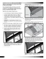
13. Verify that the pipe is level and secure the band clamp
to the underside of the second rafter using an FA4482B
Tek screw. Pipe should remain loose in the band clamp.
Band clamps support the drive pipe at each rafter
except the end rafter where the gearbox is mounted.
14. Take a section of 131S075 pipe, attach it to the first,
and secure the connection using one Tek screw.
15. Slide another band clamp onto the tapered/swaged end
of the conduit, level the conduit, and secure the band
clamp to the underside of the next rafter.
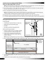
16. Continue adding conduit and band clamps and work
toward the other end of the frame. Verify that the drive
pipe remains level throughout the length.
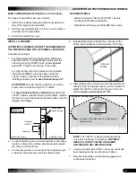
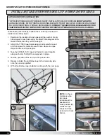
Attach one
band clamp to the inside of each rafter.
17. Select the final section of plain pipe (131P0XX where
XX represents the length needed to reach the end of
your building. Consult side profile diagram for pipe
identification.)
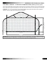
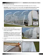
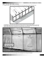
See page 60 for enlarged photo.
Interior Rafter
Drive Pipe
106734 Band
Clamp
As seen from
the inside.
Photo shows the
fully assembled
drop-down panel
from the inside
of a sample high
tunnel.
Panel is
installed later.
Drive Pipe
Ribbon Board
As seen from
the inside.
Band Clamp


