background image

GROWSPAN

 ROUND PRO GREENHOUSES AND SYSTEMS

16

Revision date: 01.23.19

END WALL INSTALLATION (continued)

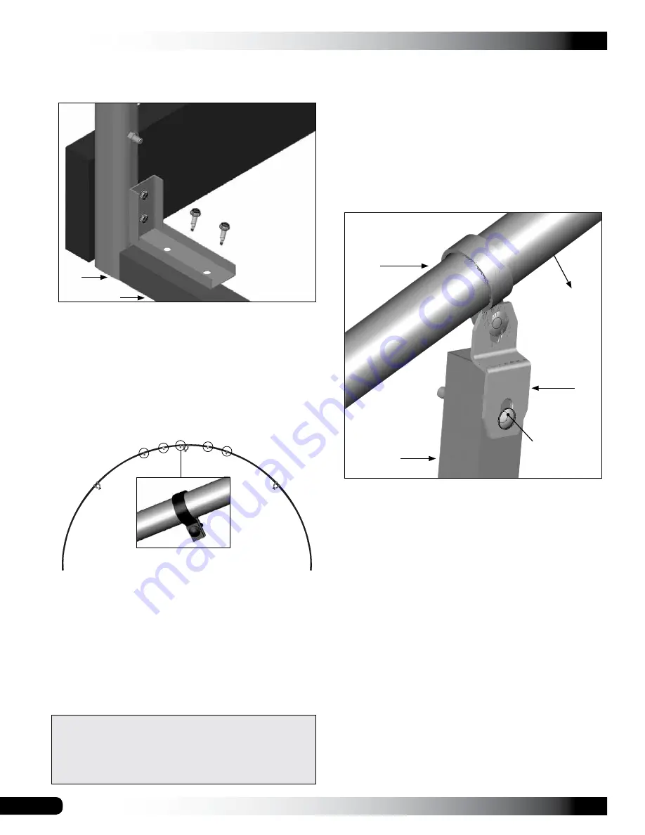
4.  Secure base tube between end rafter ground posts 

using angle brackets and Tek screws.

5.  On base tube surface facing inside the greenhouse, 

install a short Tek screw at each joint and then locate 

and mark center of base tube.

6.  Consult End Frame diagram (Quick Start section) and 

mark rough opening for width of double door assembly.

7.  Place five (5) band clamps on end rafter above door 

as shown below. 

DO NOT TIGHTEN BOLTS AT THIS 

TIME.

8.  Select tubing for the two vertical frame supports for the 

sides of the double door. 

Each support

 includes:

•  Square tubing (#102897 swaged end): For the 

longer vertical frame members, shorter sections of 

tube may need to be cut and added.

•  One (1) square-to-round tube bracket (#104074)

9.  Measure distance 

between top of base tube and 

band clamp (Step 7)

 to determine length of first frame 

member of door frame.

10. Choose one square tube (#102897), insert swaged 

end of tube into plain end of another tube. Tap with a 

hammer to properly seat tubes at joint.

11.  On this assembled frame member, mark length 

determined in Step 9 (above) and 

subtract amount 

needed to account for square-to-round tube connect 

bracket

, which is attached to top of frame tube. See 

diagram that follows.

12. Select a square-to-round tube connect bracket and 

attach bracket to one end of door jamb. Use a 5/16" 

drill bit to drill a hole through tube and attach bracket 

using a nut and carriage bolt 

(FAH320B & FALB32B)

.

13. Repeat steps to construct remaining vertical frame 

member for door.

14. With square-to-round tube connect bracket attached 

to top of each vertical door frame tube, use bolt in 

band clamp to attach bracket to band clamp. DO NOT 

TIGHTEN AT THIS TIME. 


NOTE:

 Position bolt heads for each clamp to the 

outside (or front/back) of greenhouse. At this point, 

two vertical door frame members should be loosely 

attached to end rafter.

The bracket 

shown in this 

diagram can 

be installed 

with either its 

short section 

(as shown) or 

the long section 

attached to the 

ground post.

Base Tube

Ground 

Post

ATTENTION:

 Some diagrams may shown only three 

(3) band clamps; end wall has been redesigned to 

include five (5) band clamps above the door opening. 

See End Wall diagrams in Quick Start Guide near back 

of this guide.

End Rafter

Square-to-

Round Tube 

Connect 

Bracket

Front (or outside) 

of the greenhouse

Door Jamb

FAH320B 

& FALB32B 

carriage bolt 

& nut

Summary of Contents for Round Pro

Page 1: ...20 W x 10 7 H x 20 L 104854 20 W x 10 7 H x 24 L 104855 20 W x 10 7 H x 36 L 104856 20 W x 10 7 H x 48 L 2019 GrowSpan All Rights Reserved Reproduction is prohibited without permission Photo may show...

Page 2: ...u determine whether your selected location is the best location Never erect the structure under power lines Identify whether underground cables and pipes are present before preparing the site or ancho...

Page 3: ...ladding and door 12 Install roof cladding 13 Read the care and maintenance information in next column 14 Complete and return all warranty documents as instructed SHELTER CARE AND MAINTENANCE Proper ca...

Page 4: ...tal and polycarbonate panels Wrenches and impact socket set or an adjustable wrench Scissors utility knife or tin snips Hammers rubber mallet and gloves Flat bar or putty knives for panel installation...

Page 5: ...l Spring CC6212 Fabric Clip FA4482B Tek Screw QH1402 Band Clamp 102548 Cross Connector 104074 Square to Round Tube Connect Bracket 102856 End Clamp FAH009B FALB01B Carriage Bolt Hex Nut 103496 Gearbox...

Page 6: ...does not allow channel side out installation Use the diagrams on this page to install H channel with flat side facing out ATTENTION Use only 1 1 2 Tek screws to attach H channel to building frame Do...

Page 7: ...oss connectors and purlins Ground Post Purlins Frame shown may differ slightly from actual frame Strut GrowSpan Round Pro Greenhouses and Systems OVERVIEW This section describes assembling your greenh...

Page 8: ...st 6 Repeat the same step for the last corner post NOTE The distance measured diagonally between corner posts must be equal for the building to be square 7 Check all dimensions and adjust if needed be...

Page 9: ...assemble the first end rafter and arrange on a level surface 2 Slide three 3 end purlin clamps over the rafter pipes 20R1601D 20R1601 20R1602 NOTE Consult the Front Profile diagram in the Quick Start...

Page 10: ...rafters do not use end clamps Instead cross connectors are attached during the frame assembly 2 Insert the swaged ends of the rafter pipes into the plain ends of the pipes and secure each joint with...

Page 11: ...ground posts Brace the rafter in place to keep it straight Depending on the frame size a lift and additional assistants may be needed Consult Quick Start section for details Rafter shown differs in d...

Page 12: ...fter 13 Repeat steps to add purlin pipe 131S075 and cross connectors to secure interior rafter to frame assembly 7 Tighten the end clamp and secure it to the rafter with a Tek screw Secure purlin pipe...

Page 13: ...erify you have correctly assembled purlins using correct pipes before cutting any pipe to length Review Side Profile diagram for you building in Quick Start section 20 Return to each pipe splice of ea...

Page 14: ...section for additional details 2 Attach strut upper end to end rafter band clamp Install clamp if needed Adjust strut position so lower end of strut reaches band clamp on second rafter Install that b...

Page 15: ...showing polycarbonate panel locations and locations of aluminum trim and profile before repositioning any end wall vertical DO NOT MOVE END WALL VERTICALS USED AT THE SEAM OF TWO 2 POLYCARBONATE PANEL...

Page 16: ...mark length determined in Step 9 above and subtract amount needed to account for square to round tube connect bracket which is attached to top of frame tube See diagram that follows 12 Select a square...

Page 17: ...Center of Door Frame Tube 17 Using a level or other means plumb one door frame tube and tighten band clamp bolt to secure 18 Choose square tube for header and cut swaged end to proper length for widt...

Page 18: ...ll screws bolts and clamps so they will not damage the end wall panels when panels are attached to the end wall frame End Rafter 27 Verify vertical frame member is plumb and use short Tek screws to se...

Page 19: ...o required lengths and attach to construct base tube 2 Attach vertical frame supports at top and bottom as previously described 3 Continue by installing end panels TAPE SHARP EDGES AND CONNECTORS Afte...

Page 20: ...fter removing protective film if needed ATTENTION Remove protective film from panels before installation Do not allow film to remain intact and in direct sunlight doing so will make film difficult if...

Page 21: ...stalled and cut to fit then apply foil tape to seal open cells at top as described above Flashing is installed after panel installation is complete ATTENTION Remove protective film from panels before...

Page 22: ...Diagram shows basic panel installation and fasteners used to secure polycarbonate panels Install H channel with flat side out Complete these general steps to install end panels 1 Consult panel locatio...

Page 23: ...along remaining side of door B Install 104213 u profile to finish bottom edge of panels at base tube B A END PANEL INSTALLATION continued 6 Continue to prepare and install panels and aluminum profile...

Page 24: ...e of lower panels if this is not completed yet 10 Apply foil tape DH8007 to cover open cells of all panels along radius of end rafter See arrows below END PANEL INSTALLATION continued 11 Repeat proced...

Page 25: ...25 GROWSPAN ROUND PRO GREENHOUSES AND SYSTEMS Revision date 01 23 19 Reserved for Customer Notes...

Page 26: ...USES AND SYSTEMS 26 Revision date 01 23 19 QUICK START GUIDE 20 Round Pro Greenhouse 20 0 5 8 Width 10 3 5 16 Height Grid Represents 12 Squares FRONT Ground Level Frame shown may differ in length from...

Page 27: ...27 GROWSPAN ROUND PRO GREENHOUSES AND SYSTEMS Revision date 01 23 19 FRONT PROFILE 102675 1 90 Ground Post 102675 1 90 Ground Post 20R1601D 20R1601D 20R1602 20R1601 Ground Level...

Page 28: ...OUND PRO GREENHOUSES AND SYSTEMS 28 Revision date 01 23 19 SIDE PROFILE 104853 20 0 Length Purlin Run 3 131S075 1 131P0255 4 0 on center Rafter Spacing center to center Customer Supplied Baseboard Gro...

Page 29: ...N ROUND PRO GREENHOUSES AND SYSTEMS Revision date 01 23 19 SIDE PROFILE 104854 24 0 Length Purlin Run 3 131S075 1 131P0735 4 0 on center Rafter Spacing center to center Customer Supplied Baseboard Gro...

Page 30: ...OUND PRO GREENHOUSES AND SYSTEMS 30 Revision date 01 23 19 SIDE PROFILE 104855 Purlin Run 5 131S075 1 131P0735 36 0 Length 4 0 on center Rafter Spacing center to center Customer Supplied Baseboard Gro...

Page 31: ...N ROUND PRO GREENHOUSES AND SYSTEMS Revision date 01 23 19 SIDE PROFILE 104856 Purlin Run 7 131S075 1 131P0735 4 0 on center Rafter Spacing 48 0 Length center to center Customer Supplied Baseboard Gro...

Page 32: ...MS 32 Revision date 01 23 19 CONNECTIONS Endwall Baserail Connection View 3 Vertical Horizontal Connection View 4 Endwall Rafter Connection View 5 Purlin End Rafter Connection View 1 Purlin Mid Rafter...

Page 33: ...ter Connection 102856 1 66 Purlin End Connector Rafter Purlin 102548 1 66 Cross Connector Rafter Purlin Horizontal Rail QH1330 Endwall 104624 1 Way Connector Baserail Endwall View 3 Endwall Baserail C...

Page 34: ...M FRONT VIEW 92 1 4 INSIDE DIM 98 1 4 C L C L 22 7 8 C L C L 22 7 8 C L C L 48 C L C L 25 C L C L NOTE COLUMNS NOT DIMENIONED HAVE A NON CRITICAL PLACEMENT AND ARE USED FOR POLYCARBONATE SUPPORT ALL E...

Page 35: ...RAME DIAGRAM BACK VIEW 22 7 8 C L C L 22 7 8 C L C L 48 C L C L 25 C L C L 25 C L C L NOTE COLUMNS NOT DIMENIONED HAVE A NON CRITICAL PLACEMENT AND ARE USED FOR POLYCARBONATE SUPPORT ALL END FRAMING T...

Page 36: ...does not allow channel side out installation Use the diagrams on this page to install H channel with flat side facing out ATTENTION Use only 1 1 2 Tek screws to attach H channel to building frame Do...

Page 37: ...OLY 4 X 8 POLY ONE HALF 4 X 8 POLY ONE HALF 4 X 8 POLY 6 X 10 POLY 6 X 10 POLY 4 X 8 POLY EXCESS TRIMMED AND USED HERE H CHANNEL U CHANNEL NOTE INSTALL UV PROTECTED SIDE OF PANEL TO THE OUTSIDE Ground...

Page 38: ...01 23 19 POLYCARBONATE PANELS BACK VIEW 4 X 8 POLY 4 X 8 POLY 4 X 8 POLY 4 X 8 POLY 6 X 10 POLY 6 X 10 POLY 4 X 8 POLY EXCESS TRIMMED AND USED HERE H CHANNEL NOTE INSTALL UV PROTECTED SIDE OF PANEL TO...

Page 39: ...39 GROWSPAN ROUND PRO GREENHOUSES AND SYSTEMS Revision date 01 23 19 Space below is reserved for customer notes...

Reviews: