

3-22
Revision A5
HXr Installation Manual GRT Avionics
are used for supplying power to the engine starter. This maximizes the current available for the
starter, and may extend the life of the CCFL backlight in the display unit.
The display units include internal thermally-activated fuses. This protects the equipment from
internal electrical faults. Power supplied to the EFIS must pass through an external fuse or circuit
breaker. It should be sized to allow at least 2 amps per display unit, with a maximum rating of 5
amps.
The AHRS and display units monitor all of their power inputs, and alarms are available to annunciate
the loss of any power source that was provided and is expected to be working according to the
“General Setup” menu.
3.3 Ground Connections
The cable assembly provided includes 22 gauge wire for the ground return of the display units.
This will result in a voltage drop of about 0.015 V/foot, which is acceptable for wire lengths up to
10 feet.
3.4 AHRS & OAT Wiring
The AHRS & magnetometer cable supplied with the EFIS does not have a D-sub connector installed
on the display unit or magnetometer cable end. This makes it easier to route this cable through
the airplane. After the cable has been routed, the wires can be cut to length if desired, although
new D-sub pins would need to be installed. If the wires are not cut, inspect the D-sub connector
pins to verify they have not been damaged. Insert the indicated wire color into the appropriate
D-sub connector housing hole according to the appropriate pinout diagram, located in the
Appendix of this manual. If desired, the crimp-type D-sub connector can be replaced with a
solder-type connector.
All magnetometer connections are made directly to the mating AHRS. This wiring includes the
power connections necessary for the magnetometer to operate. Each AHRS and magnetometer
pair is calibrated together for optimal accuracy, and thus this paring should be maintained.
An OAT sensor may be connected to the AHRS package to provide OAT for true airspeed
calculations. More commonly, the OAT is connected to EIS.
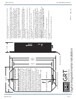
3.4.1 Magnetometer Wiring
The digital magnetometer may be wired to an unlimited number of Adaptive AHRS and/or
Mini-X/Mini-AP EFIS systems. This is accomplished by connecting the serial output from the
magnetometer to as many devices a desired. If a battery-backup is included in a Mini that is using
a magnetometer, we recommend wiring to it for the magnetometer power and ground, so that it
remains powered in the event the airplane is flown on this backup. Similarly, if no Mini- EFIS systems
are in the airplane, but one AHRS is provided with a battery backup, this AHRS should be used for
the magnetometer power and ground.
3.4.1 Legacy Equipment - Magnetometer (for AHRS part No AAS-) Wiring