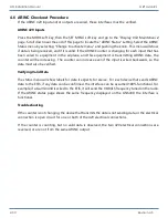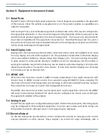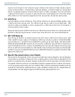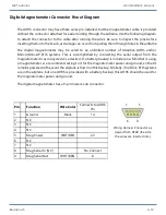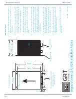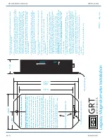
GRT Avionics HXr Installation Manual
Revision A5 A-7
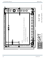
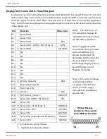
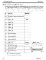
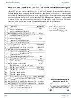
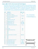
Display Unit Connector A Pinout Diagram
Connector A is a 25-Pin D-Sub female connector that attaches to the male EFIS 25-pin D-sub. Pins
that are most likely to be used are pre-installed in the connector at GRT. Commonly used optional
wires are supplied as loose wires. Wire colors and devices assigned to serial ports are suggestions
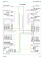
only. See HXr Interconnect Diagram for suggested system connections. NC denotes No Connection
inside display unit.
Wiring Harness
Connector A as viewed
from REAR (wired side)
Pin
Function
Wire Color
A1
Serial 6 OUT
A2
Serial 1 OUT
A3
s
Serial 5 OUT
BLU
A4
Serial 2 OUT- AHRS 1 OUT (Note 2)
BRN
A5
s
Serial 4 OUT
YEL/WHT
A6
NC
A7
NC
A8
NC
A9
NC
A10
NC
A11
NC
A12
NC
A13
NC
A14
_
Primary Power IN
RED
A15
Secondary Power IN
A16
Third Power IN
A17
_
Ground
BLK
A18
s
GPS Memory (Note 1)
RED/WHT
A19
Serial 2 IN- AHRS 1 IN (Note 2)
YEL
A20
Serial 1 IN
A21
_
Serial 4 IN - EIS IN (Note 3)
GRN/BLK
A22
s
Serial 5 IN - GPS
YEL/BLU
A23
s
Serial 3 IN
GRY/RED
A24
Serial 6 IN- Redundant AHRS (Note 2)
YEL/GRY
A25
s
Serial 3 OUT
GRY/BLK
_
Connected to wiring harness
s
Supplied as loose pinned wires
1
13
25
14
Note 1: See Section 3.7 of
HXr Installation Manual for
important information about
aircraft battery depletion.
Note 2: Suggested AHRS
connections. Wires provided
with each AHRS wiring
harness. A24/Serial 6 IN
Redundant AHRS connection
does not apply in Single
AHRS/Single Display systems.
See AHRS Interconnect
Diagram for details.
Note 3: Connector A harness
is 4 feet long with the
exception of the EIS wire,
which is 2 feet. Longer
harnesses are available by
special order.

