
HXr Installation Manual GRT Avionics
A-11
Revision A5
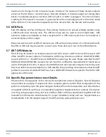
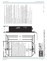
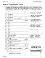
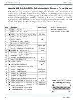
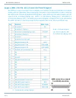
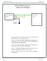
Adaptive AHRS / GSNS (GPS) / Air Data Computer Connector Pinout Diagram
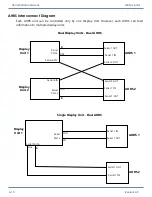
Each AHRS can only receive input from one Display Unit, however, it can send information to
multiple display units. Most dual display unit systems have a dual AHRS (one box containing two
AHRS units). In dual display/dual AHRS systems, each AHRS uses two serial outputs and one input
from its controlling Display Unit. AHRS 1 is controlled by Display Unit 1 and AHRS 2 is controlled
by Display Unit 2. See AHRS Interconnect Diagram on page A10 for more information. The AHRS
harness is 4 feet long except for the magnetometer wires, which are 20 feet long.
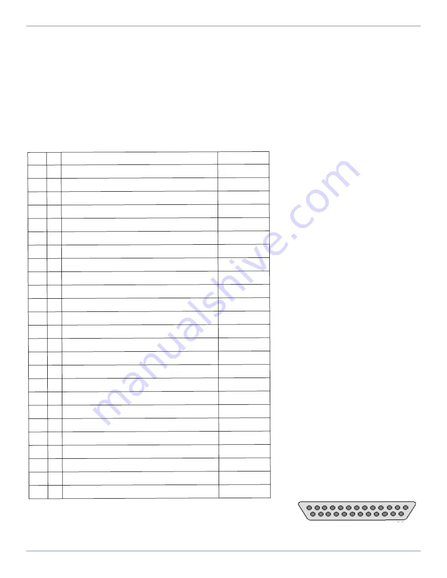
AHRS connector as viewed
from REAR (wired side)
1
13
25
14
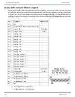
Pin
Function
Wire Color
1
_
AHRS1 Serial Out 1
YEL
2
AHRS1 Serial Out 1 (Note 1)
3
p
AHRS1 Serial Out 2 (dual display only)
YEL/GRY
4
AHRS1 Serial Out 2 (Note 1)
5
_
AHRS1 Serial In
BRN
6
Reserved - Do Not Connect
7
Reserved - Do Not Connect
8
_
Magnetometer Serial In
WHT/BRN
9
AHRS2 Power In A (9-30 Vdc, 0.1A)
RED/WHT
10
p
Outside Air Temperature IN
Gray
11
Reserved - Do Not Connect
12
Reserved - Do Not Connect
13
_
Ground (Interchangable with pin 14)
BLK
14
Magnetometer Ground
BLK
15
p
GPS Serial Out
ORANGE
16
p
GPS Serial In (Optional)
BLUE
17
AHRS2 Power In B (9-30 Vdc 0.1A)
18
AHRS2 - Serial Input
WHT/BLU
19
AHRS2 - Serial Output
YEL/WHT
20
AHRS2 - Serial Output
21
AHRS2 - Serial Output
22
Magnetometer Power OUT (4.3-5.0Vdc)
WHT/RED
23
_
AHRS1/GPS Power In A 9-30Vdc 0.15 A
RED
24
p
AHRS1/GPS Power In B 9-30Vdc 0.15 A
RED/BLU
25
p
AHRS1/GPS Power In C 9-30Vdc 0.15 A
RED/GRN
_
Wire pre-installed in connector
p
Wire included but not installed
Note 1: Extra serial port;
use only in systems with
more than two display units.