
HXr Installation Manual GRT Avionics
A-15
Revision A5
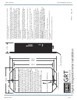
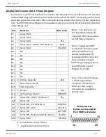
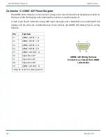
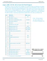
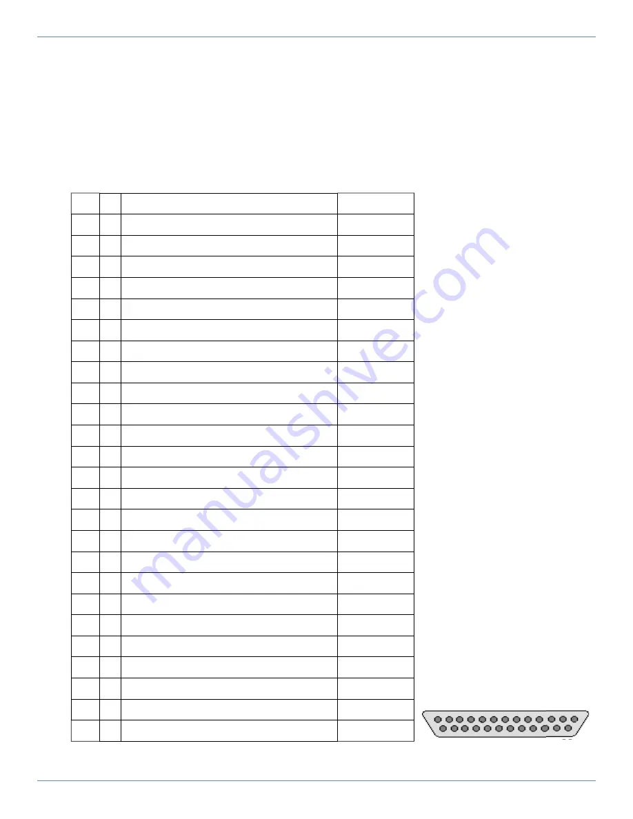
Legacy AHRS (Part No AAS-) Connector Pinout Diagram
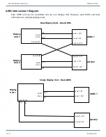
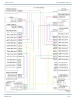
The AHRS can only receive input from one Display Unit, however, it can send information to multiple
display units for redundancy. Most dual display unit systems have a dual AHRS (one box containing
two AHRS units). In dual display/dual AHRS systems, each AHRS uses two serial outputs and one
input from its controlling Display Unit. AHRS 1 is controlled by Display Unit 1 and AHRS 2 is
controlled by Display Unit 2. See AHRS Interconnect Diagram on page A10 for more information.
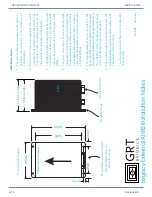
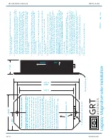
The AHRS harness is 4 feet long except for the magnetometer wires, which are 20 feet long.
Pin
Function
Wire Color
1
_
Serial Out 1
YEL
2
Serial Out 1 (Note 1)
3
_
Serial Out 2 (dual display only)
YEL/GRY
4
Serial Out 2 (Note 1)
5
_
Serial In 1
BRN
6
Serial In 2 (do not use)
7
_
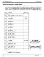
Magnetometer Z IN
WHT
8
_
Magnetometer Y IN
WHT/BRN
9
_
Magnetometer X IN
WHT/GRN
10
_
Outside Air Temperature IN
Gray
11
NC
12
NC
13
_
Ground
BLK
14
_
Magnetometer Ground
BLK
15
NC
16
NC
17
NC
18
_
Magnetometer Control OUT
WHT/BLU
19
NC
20
NC
21
NC
22
_
Magnetometer Power OUT
WHT/RED
23
_
Aircraft Power Input A
RED
24
_
Aircraft Power Input B
RED/BLU
25
_
Aircraft Power Input C
RED/GRN
_
Connected to wiring harness
AHRS connector as viewed
from REAR (wired side)
1
13
25
14
Note 1: Extra serial port;
use only in systems with
more than two display units.


