Revision A9 15
GRT Avionics Mini-X Installation, Setup & User Manual
Section 2: Wiring Considerations
2.1 Mini-X Connector Definition
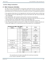
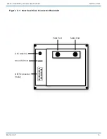
The Mini-X comes with a female DB15 connector pre-wired with the most commonly used wires.
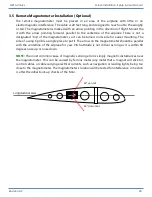
The optional remote magnetometer uses a DB9 connector and is connected to the Mini using the
pins defined below. The colors shown here correspond to the colors in the supplied wiring harness.
�
The supplied wiring harness for the magnetometer is 20 feet long; all other wires are 4 feet long.
�
The magnetometer serial output (Mag pin 9) may be shared with other GRT Avionics Mini-EFIS,
or the GADAHRS.
�
The magnetometer, OAT, serial ports and Trig TT22 connections are all optional.
�
OAT is required for true airspeed and density altitude calculations when the Mini does not have
a serial connection to a working GRT Horizon or Sport EFIS display unit.
�
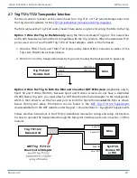
Use Trig TT22 A and B connections for control and encoder information for the TT22.
�
Any of the serial port pairs can be used for a variety of connections, including connection to
another GRT display unit for limited data sharing, serial transponder or handheld GPS.
Magnetometer DB9
Pin No.
Mini DB15
Pin No.
Use
Color
1
Serial 2 Out
YEL
2
Serial 2 In
YEL/WHT
3
Trig TT22 A
4
Trig TT22 B
5
Serial 1 Out
GRN
6
Serial 1 In
WHT/GRN
7
Ground
BLK
8
Power in: 8-30V
RED
8 (serial in)
9
Mag A/Serial 3 Out
ORG
9 (serial out)
10
Mag B/Serial 3 In
ORG/BLK or
WHT/BRN*
5 (mag power -
must be
powered by Mini-X or an adaptive
AHRS)
11
Mag C
BLU or WHT/RED*
1 (ground)
12
Mag D
WHT/BLU or BLK*
13
Audio Output
14
Audio Ground
15
OAT
GRY
*Two possible wire colors sets are possible. Pin 8, serial input, is optional,
an can only be connected to one Mini.

