


Mini-X Installation, Setup & User Manual GRT Avionics
Revision A9 18
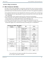
Power Inputs-
The Mini has one power input to be connected to the aircraft’s electrical system,
plus an option for an internal backup battery, which is charged through the main power input.
Voltage Monitor-
The Mini monitors its power input and backup battery level. A warning will flash
to annunciate the loss of any power source that was provided and is expected to be working
according to the “General Setup” menu.
Ground Connection-
The cable assembly provided includes 22 gauge wire for the ground return
of the Mini. This will result in a voltage drop of about 0.015 V/foot, which is acceptable for wire
lengths up to 10 feet.
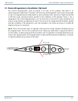
2.4 Autopilot Source Switch (Optional)
If another GRT EFIS screen is used for the primary display, wire a switch into the instrument panel
to allow the Mini to be the selected autopilot source in case the main display should fail. In normal
operations, the autopilot control signals pass through the inter-display link, allowing either the
Mini or a primary GRT EFIS to control the autopilot when both screens are functioning, regardless
of the switch position. Refer to the GRT Autopilot wiring diagrams and installation/setup manual,
downloadable from the
Support > Documentation > Autopilot section
information on wiring and setup of the GRT autopilot. (Note: In autopilot wiring & setup
documentation, the Mini is treated the same as any other type of GRT Display Unit. Pilot information
specific to Mini autopilot controls can be found in this manual.)
2.5 Magnetometer Wiring (Optional/Recommended)
The remote magnetometer must be placed in an area of the airplane with little or no
electromagnetic interference. The cable is 20 feet long and designed to reach out to the wingtip
or tail. Please refer to the magnetometer installation guidelines in Section 3.5 of this manual for
more information.
The magnetometer cable supplied with the Mini does not have a D-sub connector installed on the
magnetometer cable end. This makes it easier to route this cable through the airplane. After the
cable has been routed, the wires can be cut to length if desired. Install pins onto the ends of the
magnetometer wires. Note that they are the opposite orientation as the (Pins are not installed at
the GRT factory because experience has shown us that they are too easily damaged as they are
routed through the airplane.) Insert the indicated wire color into the appropriate D-sub connector
housing hole according to the Mini Connector Definitions diagram in Section 2.1.
The digital magnetometer serial output may be shared between any number of the Mini-X, Mini-AP,
and any Adaptive AHRS.