


Mini-X Installation, Setup & User Manual GRT Avionics
Revision A9 20
2.7 Trig TT21/TT22 Transponder Interface
The Mini is able to function as the control head for a Trig TT21 or TT22 remote transponder. Visit
the Trig Avionics website for the
TT21/22 installation manual and wiring diagrams.
The Mini replaces the Trig TC20 control head. There are two options for wiring the Mini to the Trig.
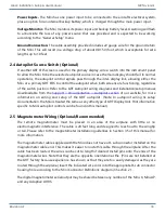
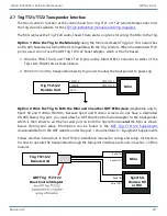
Option 1: Wire the Trig to the Mini only
using the Mini’s dedicated Trig port. This output has
an RS-485-based serial format that is compatible with the Trig controls. When the dedicated TT22
port is used, do not use the GRT Trig TT21/22 Serial Adapter, which is RS-232 based.
1. Wire the TRIG TT22 A and TRIG TT22 B pins on the Mini’s DB15 connector to either of the
Trig’s two TMAP sets as shown below.
2. Wire Pin 13 on the transponder directly to ground to allow the transponder to power up.
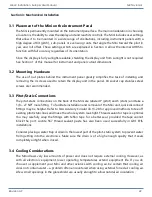
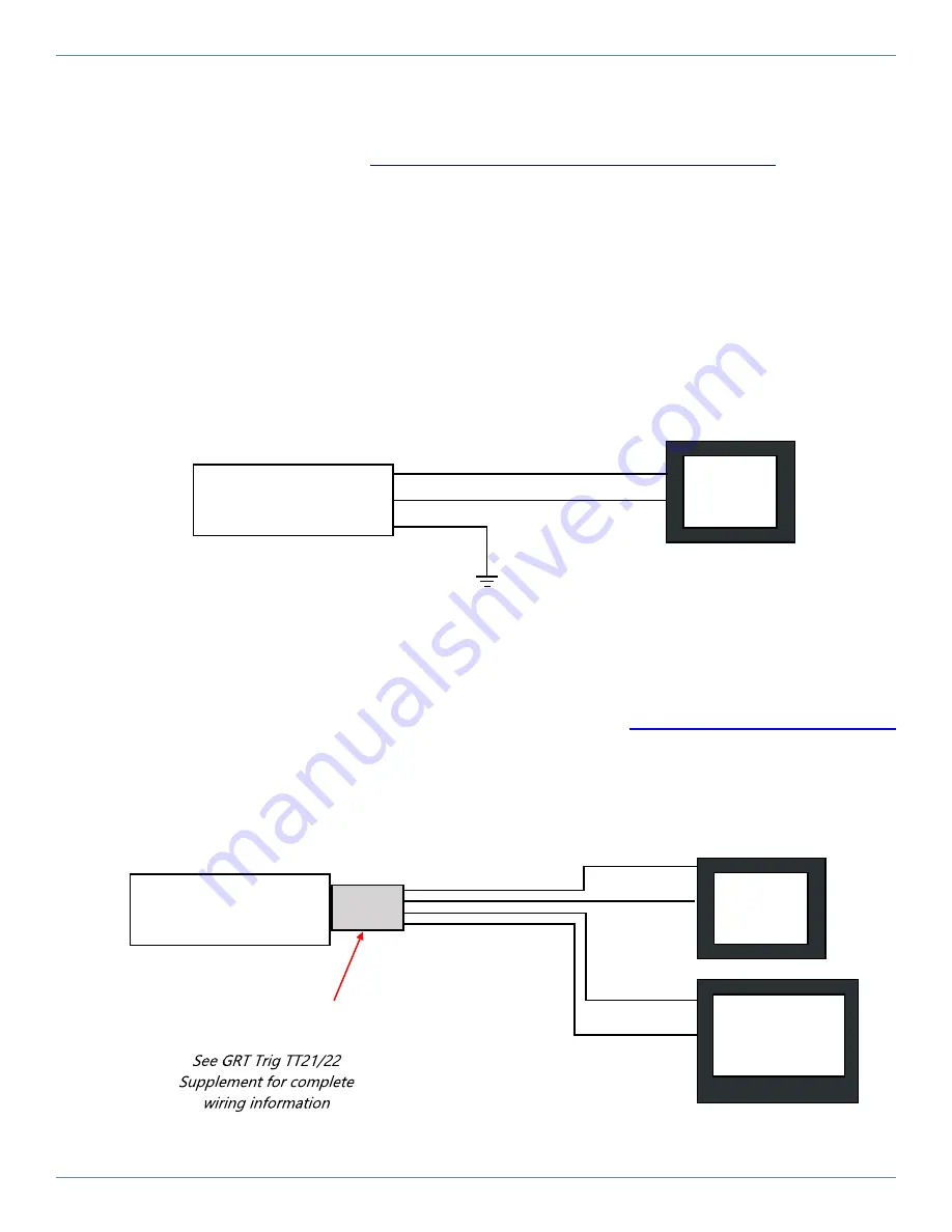
Option 2: Wire the Trig to both the Mini and one other GRT EFIS screen
(Applicable only to
Sport SX and Horizon HX/HXr). Because Sport and Horizon screens do not have a dedicated
RS-485-based Trig port, you must attach a GRT Dual-Control Serial Adapter to the transponder,
which is then wired to an RS-232 serial port on both the Sport/Horizon
and
the Mini as shown
below. Wiring and setup information can be found in the
,
downloadable from the GRT website under Support > Documentation > Equipment Supplements.
Follow all other instructions in the TT21/22 installation manual for wiring and setup. Instructions
for how to operate the transponder through the Mini pilot interface are found in Section 7 of this
manual.
Mini
Trig TT21/22
Remote Unit
TRIG TT22 A
TRIG TT22 B
TMAP1B
TMAP1A
Pin 13
Trig TT21/22
Remote Unit
Sport SX,
Horizon HX
or HXr
Mini
GRT Trig TT21/22
Dual-Control Adapter
Serial IN
Serial OUT
Serial IN
Serial OUT


