GRT Avionics, Inc.
May 2019
Sport SX Install. Manual
13
Rev. A
SECTION 3: PHYSICAL INSTALLATION
3-1: Display Unit Installation
Mount the display unit(s) in the desired location in the instrument panel. The main
consideration in choosing a location is the ability to view the display unit and reach its
controls. Since the screen is fully sunlight-readable, no consideration for shielding the
display unit from sunlight is required. Be mindful of the space behind the instrument panel
as well; some aircraft with tip-up canopies, for example, have canopy supports that may
interfere with the back of the EFIS when the canopy is closed. See the
Appendix
sections
A-
1: 6.5” Sport SX Mounting Template
,
A-
2: 8.4” Sport SX Mounting Template
,
A-3:
Sport HS Mounting Template
and
A-4: Sport WS Mounting Template
for display unit
dimensions and clearance requirements for the rear of the unit.
1. For panel-mount style display units, the use of nut plates behind the instrument
panel greatly simplify the task of installing and removing the 4 screws used to retain
the display unit in the panel. #6 socket cap stainless steel screws are
recommended.
2. For radio rack style display units, the #6 screws on the side of the unit (2 per side)
should be used to attach the display unit to the radio rack.
3-2: Remote Digital Magnetometer Installation
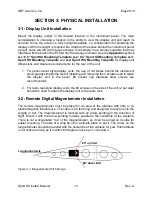
The remote magnetometer must be placed in an area of the airplane with little or no
electromagnetic interference. The cable is 20 feet long and designed to reach out to the
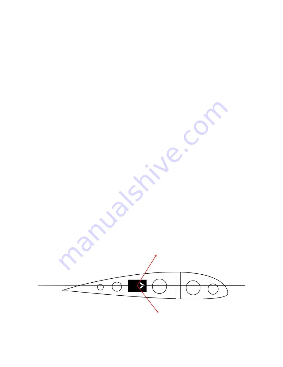
wingtip or tail. The magnetometer is marked with an arrow pointing in the direction of
flight. Mount it with the arrow pointing forward, parallel to the centerline of the airplane.
There is not a designated “top” of the magnetometer, so it can be turned on its side for
easier mounting. The side of a wing tip rib is a simple place to put it. The arrow on the
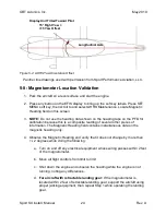
magnetometer should be parallel with the centerline of the airplane for yaw. Pitch attitude
is not critical as long as it is within 60 degrees nose up or nose down.
60° up limit
Longitudinal Axis
60° down limit
Figure 3-1: Magnetometer Pitch Range

