GRT Avionics, Inc.
May 2019
Sport SX Install. Manual
40
Rev. A
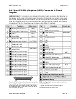
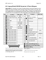
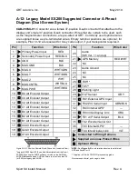
A-9: Legacy Model SX200 Connector A Pinout Diagram
CAB-200SX-01:
Connector A is a female 37-position D-sub connector that attaches to the
display unit’s male 37-position D-sub connector. Wires that are certain to be used, such
as the magnetometer connections, are pre-wired at GRT. Commonly used optional wires
are supplied loose as pre-terminated wires. Empty terminal positions are optional; for
example, Pins 10-19 are reserved for Grey code output, if your transponder requires it.
Figure A-9: 37 Position Female D-sub Connector (Insertion View)
* NOTE:
See
Figure A-5
for information about optional Internal
GPS and Serial Port 3.
* Legacy SX200 Sport EFIS can be differentiated from the Sport
SX200A by noting the AHRS software version on the Set Menu,
**:
Applies to SX with CPU/GPU processor upgrade.
AHRS Maintenance page. AHRS software versions less than 50
(or 0.50) are legacy type AHRS.
Recommended serial port usage in italics.
Pin
Function
Wire Color
20
Audio
(SW Ver. 11 and up)
21
GPS Memory
RED/WHT
22
NC
23
Audio Ground
24
NC
25
NC
26
RX5**
27
TX5**
28
Warning Light
29
OAT Sensor
GRY
30
RX1
External GPS Input
31
RX2
EIS Serial Input
GRN/BLK
32
RX3 Internal GPS*
―
33
RX4
34
TX1
A/P Serial Output
BLU
35
TX2
Encoder Serial Out
36
TX3 Internal GPS*
―
37
TX4
Connected in Wiring Harness
Supplied as Loose Pinned Wires
Optional Wiring
Pin
Function
Wire Color
1
Primary Power Input
RED
2
Secondary Power Input
RED/BLU
3
GND
BLK
4
MAG GND
BLK
5
MAG X
WHT/GRN
6
MAG Y
WHT/BRN
7
MAG Z
WHT
8
MAG CNTRL
WHT/BLU
9
MAG PWR
WHT/RED
10
D4 Alt Encoder Output
11
C4 Alt Encoder Output
12
C2 Alt Encoder Output
13
C1 Alt Encoder Output
14
B4 Alt Encoder Output
15
B2 Alt Encoder Output
16
B1 Alt Encoder Output
17
A4 Alt Encoder Output
18
A2 Alt Encoder Output
19
A1 Alt Encoder Output

