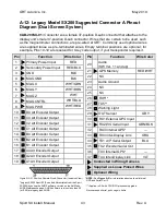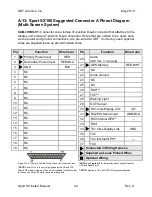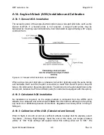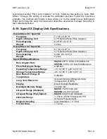
GRT Avionics, Inc.
May 2019
Sport SX Install. Manual
41
Rev. A
A-10: Magnetometer
– Digital and Analog (Legacy)
CAB-SX200A-01/CAB-200SX-01:
The Connector A harness comes with the
magnetometer wires installed in its connector housing; a mating 9-position D-sub
connector and set of D-sub terminals are also included for installation after the wires have
been run through the airframe (Female/sockets to attach to
the Digital Magnetometer’s
male connector and male/pins to attach to
the Analog Magnetometer’s female connector).
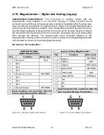
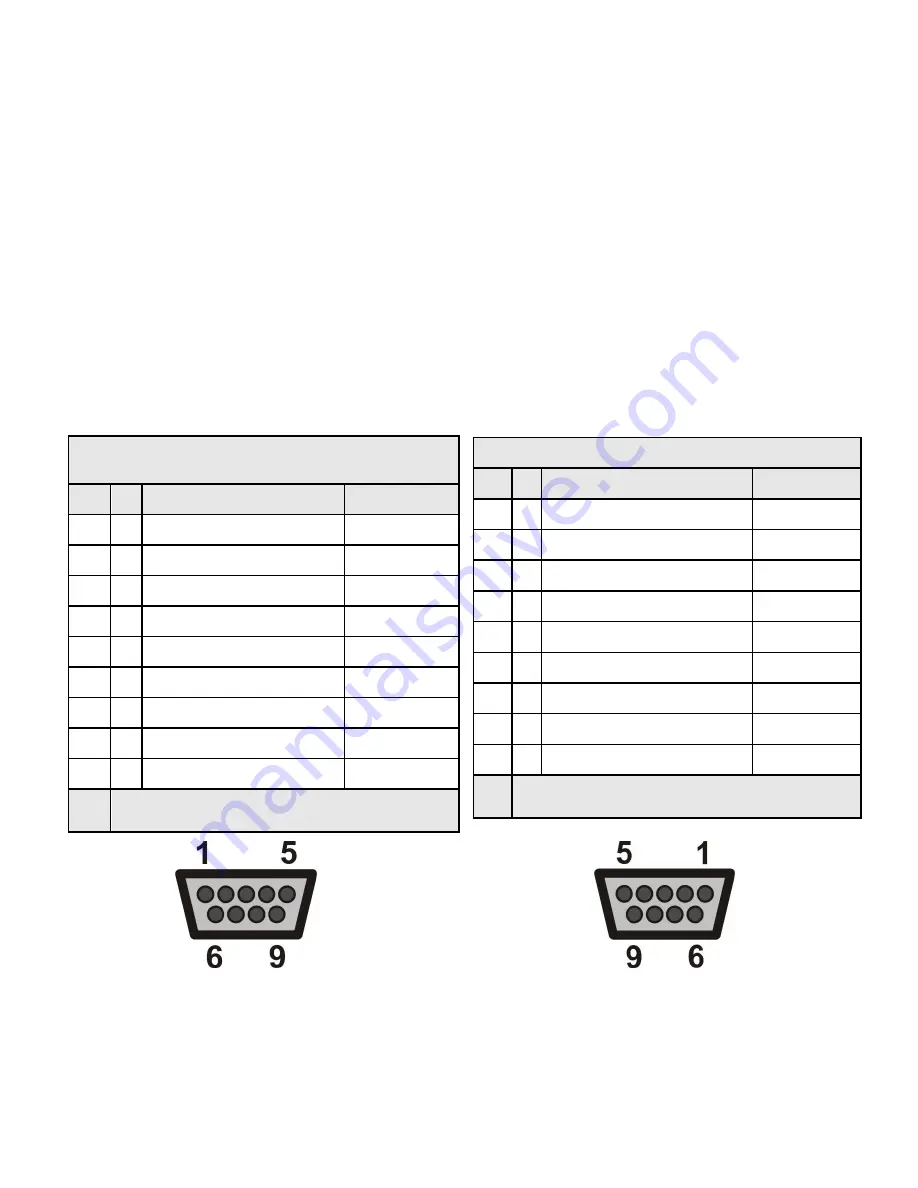
Use the following diagram to plug the wires into the connector housing. Be sure to inspect
the terminals before inserting them into the connector, as damage may occur while pulling
them through the airframe. The magnetometer wires’ connector attaches to the
magn
etometer’s mating D-sub connector (A male connector for the Digital Magnetometer
and a female connector for the Analog Magnetometer).
NC
denotes “No Connection.”
Figure A-10: 9 Position Female D-sub Connector Figure A-11: 9 Position Male D-sub Connector
CAB-SPORT-MAG
Digital Magnetometer
Pin
Function
Wire Color
1
I
Ground
BLK
2
NC
3
NC
4
NC
5
I
Power In (+4.3V)
WHT/RED
6
NC
7
NC
8
NC
9
I
Serial Output
WHT/BRN
I
Insert terminal into connector after the
wire is pulled through the airframe.
Legacy Analog Magnetometer
Pin
Function
Wire Color
1
I
MAG Y
WHT/BRN
2
I
MAG Z
WHT
3
I
MAG X
WHT/GRN
4
I
MAG PWR
WHT/RED
5
I
MAG GND
BLK
6
I
MAG CNTRL
WHT/BLU
7
NC
8
NC
9
NC
I
Insert terminal into connector after the
wire is pulled through the airframe.

