GRT Avionics, Inc.
May 2019
Sport SX Install. Manual
44
Rev. A
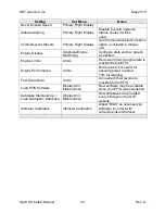
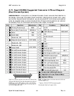
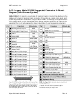
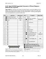
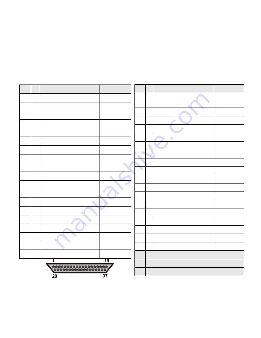
A-13: Sport SX100 Suggested Connector A Pinout Diagram
(Multi-Screen System)
CAB-100SX-01:
Connector A is a female 37-position D-sub connector that attaches to the
display unit’s male 37-position D-sub connector. Wires that are certain to be used, such
as the power and ground connections, are pre-wired at GRT. Commonly used optional
wires are supplied loose as pre-terminated wires.
Figure A-9: 37 Position Female D-sub Connector (Insertion View)
**NOTE:
See
Figure A-5
for information about optional Internal
GPS and Serial Port 3.
*NOTE:
Serial Port 4 is the only high-speed port in HS and WS
Sport EFIS models, making it the only port suitable for XM Weather
***NOTE:
Applies to SX with CPU/GPU processor upgrade.
in these units. All five SX serial ports are high-speed.
Pin
Function
Wire Color
20
Audio
(SW Ver. 11 and up)
21
GPS Memory
RED/WHT
22
NC
23
Audio Ground
24
NC
25
NC
26
RX5***
27
TX5***
28
Warning Light
29
OAT Sensor
30
RX1 Inter-Display Link
VLT
31
RX2 EIS Serial Input
GRN/BLK
32
RX3 Internal GPS**
―
33
RX4*
34
TX1 Inter-Display Link
ORG
35
TX2
36
TX3 Internal GPS**
―
37
TX4
Connected in Wiring Harness
Supplied as Loose Pinned Wires
Optional Wiring
Pin
Function
Wire Color
1
Primary Power Input
RED
2
Secondary Power Input
RED/BLU
3
GND
BLK
4
NC
5
NC
6
NC
7
NC
8
NC
9
NC
10
NC
11
NC
12
NC
13
NC
14
NC
15
NC
16
NC
17
NC
18
NC
19
NC