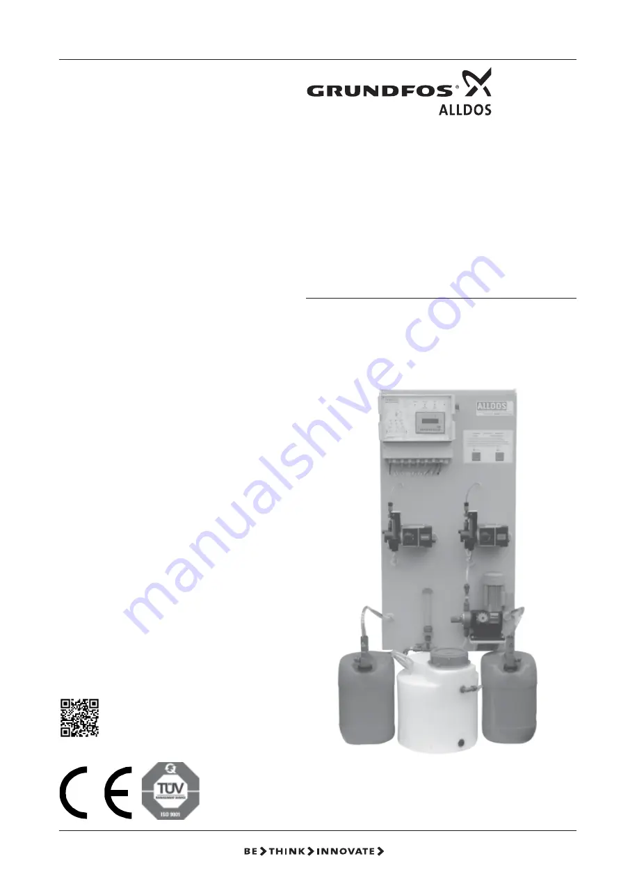
background image

1

Oxiperm

®

  C 164

Fully-automatic Chlorine Dioxi-
de Generation System
164 -150C, -450C, -750C,

-1300C, -2500C

Operation and
Service Manual

Please read the Operation Manual completely and retain for future reference!

Damages resulting from operating errors cancel the guarantee.

Other languages

http://net.grundfos.com/qr/i/96681303

Summary of Contents for Oxiperm C 164 Series

Page 1: ...on System 164 150C 450C 750C 1300C 2500C Operation and Service Manual Please read the Operation Manual completely and retain for future reference Damages resulting from operating errors cancel the gua...

Page 2: ...automatic chlorine dioxide generation system 164 150C 450C 750C 1300C 2500C Operation and Service Manual Version 5 0 Issued by ALLDOS Eichler GmbH Reetzstra e 85 D 76327 Pfinztal S llingen Postfach 11...

Page 3: ...ollowing commissioning It will help you and your Grundfos Alldos servicing partner to adjust the device during subsequent corrections Owner Grundfos Alldos customer No Contract No Order No of device S...

Page 4: ...Reactor 17 5 2 5 Bypass Line 17 5 2 6 Post mixer 17 5 2 7 Purging Unit 17 5 2 8 Preliminary Water Tank 18 5 2 9 Options 18 5 3 Mode of Operation of System 20 5 3 1 How the system operates in batch mo...

Page 5: ...ng Pumps for NaClO2 HCl and H2O 48 7 8 2 Startup Mode 49 7 8 3 Test Mode 50 7 8 4 Reactor Purging 51 7 8 5 Reactor Temperature 51 7 9 Local Remote 52 8 Startup 53 8 1 Installation selection 54 8 2 Mod...

Page 6: ...nce of Suction Lines 95 11 3 Maintenance of Reactor 95 11 4 Maintenance of Suction Injector 97 12 Details on theVersions 99 12 1 Housing Suction 99 12 2 Solenoid Valve 100 12 3 Flow Limiter Vane Anemo...

Page 7: ...w The safety instructions WARNING CAUTION NOTE and PACKAGING have the following meanings WARNING Danger of injuries and accidents CAUTION Danger of malfunctioning or damage to device NOTE Exceptional...

Page 8: ...for training of operating personnel and implementation of regular maintenance 2 3 Avoidance of Danger WARNING Before starting up it is essential that you read the Grundfos Alldos information document...

Page 9: ...Permissible process water temperature bypass water 2 C to 40 C Permissible component temperature chemicals 5 C to 30 C Storage temperature of system 5 C to 50 C Storage temperature of chemicals 5 C t...

Page 10: ...at the Oxiperm C164 outlet as a result of a correspondingly high input pressure at the Oxiperm C164 inlet in the dilution water line System System weight Suction connection DN kg 164 150C 20 58 164 45...

Page 11: ...760 70 130 1340 1300 258 156 475 11 DN 20 DN 20 164 450C 820 760 70 130 1340 1300 258 156 475 11 DN 20 DN 20 164 750C 820 760 70 130 1340 1300 258 156 475 11 DN 20 DN 20 164 1300C 850 790 70 130 1460...

Page 12: ...er 3 3 DeliveryState The Oxiperm C 164 compact chlorine dioxide system comprises The generation system completely assembled and wired up on a PP system frame including dosing pumps and suction line an...

Page 13: ...ds of high molecular weight Good stability in water Long bactericidal and bacteriostatic protection in the water network 4 1 1 Generation of Chlorine Dioxide The Oxiperm C 164 was specially developed...

Page 14: ...eaction between hydrochloric acid and sodium chlorite to the right resulting in an optimum yield 4 2 Functional Sequence Three components are required to generate a chlorine dioxide solution Hydrochlo...

Page 15: ...ng pump for sodium chlorite Item 2 2 Suction line with advanced and main empty alarm for NaClO2 blue Item 2 3 Dosing controller for NaClO2 flow monitoring 3 Bypass water line Item 3 1 Solenoid valve c...

Page 16: ...2 Dosing Pumps The dosing pumps are mounted at the bottom end of the system frame The suction ends of the suction lines lead to the pumps The stroke length is adjusted using a rotary knob on the dosi...

Page 17: ...he water in the bypass is monitored by a flowmeter which switches the system off if the bypass water falls below a minimum flow Falling below the minimum water quantity is also indicated by a flashing...

Page 18: ...t B021 Bypass line with solenoid valve 115 V 50 60 Hz and flow limiter Purging with solenoid valve drain unit B022 Bypass line with pump 230 V 50 Hz Purging with solenoid valve drain unit B023 Bypass...

Page 19: ...ction DN20 230 V 50 60 Hz A04 Housing suction DN20 115 V 50 60 Hz A02 Without housing suction standard version Reactor check valves Code Description R003 System back pressure less than 3 bar standard...

Page 20: ...ects a low flow WARNING Chlorine dioxide is a toxic gas Hydrochloric acid and sodium chlorite are highly corrosive chemicals which must be handled properly Installation and operating personnel must th...

Page 21: ...concentrations below 2 g l the required quantity of bypass water for a 2 g l solution is set and the desired concentration inside the solution container is then achieved by regulating the two dosing...

Page 22: ...regulations 6 3 InstallationLocation NOTE The applicable local or country specific regulations must be observed when selecting and designing the installation location for the chlorine dioxide system T...

Page 23: ...chemicals can easily flow back via the return pipe into the container recommended L min 200mm see diagram Legend Item 1 Oxiperm 164 system frame Item 2 Oxiperm 164 electronics Item 3 Connection for di...

Page 24: ...in the same water circuit A requirement for correct functioning of the system is a water pressure of at least 1 bar up to maximum 10 bar In addition the back pressure at the connection of the solutio...

Page 25: ...i e the sampling of dilution water and the addition of chlorine dioxide solution are present in the same water circuit The bypass pump is only designed for compensation of the internal friction losse...

Page 26: ...e tank can be adjusted from 2 to 3 3 g l With this arrangement a pressure retention valve item 16 must be used between the system and the solution tank The pressure set on the retention valve depends...

Page 27: ...option This version is required if sampling of the dilution water and addition of the chlorine dioxide solution are not in the same water circuit and the system pressure at the injector is higher than...

Page 28: ...bypass internal pump bypass solenoid valve ball valve bypass external pump The drain unit item 17 is installed between the injector and the system The drain line item 18 is directly connected to a neu...

Page 29: ...ble to insert the suction lines items 5 and 6 for hydrochloric acid and sodium chlorite into the tanks without tension Install the suction hose return hose and the two empty alarm cables of the suctio...

Page 30: ...ed screwed gland of the system frame in the center of the base CAUTION The forcing water of the suction injector must be free from sand and suspended matter It is therefore recommendable to install a...

Page 31: ...i e the required inlet pressure for the suction injector has to be generated using a booster pump item 6 If the water quantity in the inlet line item 5 is sufficient water sufficient for bypass and su...

Page 32: ...wer supply each time the system is connected A direct connection of the system to the power supply is made using the terminals 1 L1 2 N and 3 PE Depending on the version the power supply can be 230 V...

Page 33: ...max N O contact Contact closed in case of MAX ClO2 level above contact 47 48 Batch tank_ClO2 min N O contact Contact closed in case of MIN ClO2 level below contact 49 50 Batch tank_ClO2 run dry N O co...

Page 34: ...34 15 710010 V5 0 Oxiperm 164 150 2500 g en...

Page 35: ...TxD P 2 RxD TxD N 1 PGND 0 RTS Signal Meaning Plug CNTR P RTS Control signal 0 for repeater PGND Shield 1 protective earth RxD TxD N Received data 2 transmitted data Negative RxD TxD P Received data...

Page 36: ...RS232 RS422 485 Interface As a further option the controller of the Oxiperm C164 can be equipped with interfaces RS 232 See following Fig for connection of the RS232 interface RS 422 485 See followin...

Page 37: ...e Main menu System type Operating mode Type 1 Type 2 etc Batch mode Current input Contact input Manual control Language Min contact water Current output Code function Reset Function Date time Venting...

Page 38: ...5 LED for HCl tank LED off level OK LED flashes advanced empty alarm LED on empty alarm Item 6 Arrow keys for moving in the display menus Item 7 Function keys F1 F2 and F3 Selection possibility for i...

Page 39: ...shes when the dosing controller is correctly set The selection possibilities shown on the display are identified by the numbers 1 2 and 3 e g Main menu 1 Automatic mode 2 Manual mode 3 Logbook Menu se...

Page 40: ...ng on the display 7 4 Manual Mode This operating mode Betriebsmodus facilitates the manual input of the dosing capacity by the display in the modes current input contact input manual control or Bus co...

Page 41: ...he system is preset in the factory i e the selected type of system is displayed flashing in the System selection menu Check this setting for correctness prior to starting up or select a new system typ...

Page 42: ...rol of the installation capacity from 2 5 100 using a bus system can only be selected if a bus system has been selected in the Basic settings Bus menu NOTE The mode is factory set i e the selected mod...

Page 43: ...played flashing in the Min contact water menu 7 7 3 Current Output In the Basic setting menu select the Current output menu using the F3 key Display Current output ClO2 performance 0 XX mA 100 YY mA P...

Page 44: ...field using F1 key Input of code analogous to level 1 Use the Enter or Escape key to return to the Code function menu Use Escape key again to return to Basic setting menu 7 7 5 Reset Function In the...

Page 45: ...setting New Current XX YY ZZ 15 04 02 2 Accept Switch to the Day of week menu using the Arrow right key and back to the Date setting menu using the Arrow left key Display Day of week New Current XX Mo...

Page 46: ...g menu 7 7 7 Housing Suction The housing suction is used to regularly exchange the air in the system frame of the Oxiperm C 164 The suction is time controlled defined by switch on and switch off times...

Page 47: ...Use the Enter or Escape key to return to the Basic setting menu Use the Escape key to return to the main menu 7 7 10MIN Bypass Time In the Basic setting menu switch to the MIN bypass time display usi...

Page 48: ...will restart automatically following a set pause time The number of start attempts cycles is configurable Pause time 1 to 10 minutes No of cycles 0 10 Cycles set to 0 Automatic start function not acti...

Page 49: ...g pump Use the Escape key to return to the Service mode menu 7 8 2 Startup Mode Startup mode is used to fill the reactor with water Filling is carried out using the dosing pump for H2O the pumps for H...

Page 50: ...atically at the end of the startup time Display Startup mode finished NOTE If startup mode is cancelled prematurely and then restarted the startup time commences again at approx 40 minutes Use the Esc...

Page 51: ...nance or repair work if the system is equipped with a purging solenoid valve and a drain unit In the Service mode menu switch to page 2 using the Arrow right key Display Service mode 1 Reactor purging...

Page 52: ...oll with the arrow right key in the main menu Switch to the local remote menu with the F1 key Display shows local remote 1 local control 2 remote control Select control mode with the F1 or F2 key Disp...

Page 53: ...sure conditions loosen the screw underneath the stroke adjustment knob and readjust the dosing pump to the required consumption data if necessary Then tighten the stroke adjustment knob again to preve...

Page 54: ...the installation type has been selected the following message appears on the display Display indicator Installation type 164 XXXD activated Press Enter or Escape to return to the Installation Selecti...

Page 55: ...lay indicator Main menu 1 Automatic 2 Manual 3 Logbook Use the arrow right button in the main menu to switch to page 2 Display indicator Main menu 1 Installation selection 2 Basic settings 3 Service m...

Page 56: ...lection 2 Basic settings 3 Service mode Press F3 to switch to Service Mode The display reads Service Mode 1 Deaeration 2 Start up mode 3 Test mode Press F2 to switch to the Startup Mode menu from the...

Page 57: ...nter the value to be added Press F1 to switch to the variable field max flow H2O and enter the max volume of water Press Enter to confirm Press Enter again to switch to the menu Display indicator Curr...

Page 58: ...itch to the variable field 0000 0 m h and enter the max flowrate enter with the up down arrow left arrow right buttons analogous to the current input entry Press Enter to confirm Press Enter or Arrow...

Page 59: ...nter to switch to the menu Display indicator Contact input Flow of H2O Max xxx x m h Min xxx x m h The max and min volume of water which can be supplied with ClO2 through the set quantity to be added...

Page 60: ...Mode menu NOTE In Manual Control mode the installation can only be started in manual mode 8 2 5 Target value external Press arrow right to scroll within the Mode menu Display indicator Mode Page 2 1...

Page 61: ...e bypass line solenoid valve or bypass pump Bypass ON appears on the display The bypass line in the installation can now be deaerated 8 3 1 Bypass pump option Press F1 to activate or deactivate the by...

Page 62: ...3 2 Filling the Water Tank The preliminary water tank is filled when water flows through the bypass line of the system i e solenoid valve bypass pump active Press F1 to switch to the Deaeration menu...

Page 63: ...H2O off See also Section 7 8 1 Venting NOTE If the stroke setting is changed when venting the preset stroke length must be set again following the venting procedure Activate the dosing pump using the...

Page 64: ...atch to determine the time required to dose a certain quantity of water and calculate the dosing performance Example 350 ml in 180 seconds V l h 350 ml x 3600 s 180 s x 1 1000 V l h 7 l h Following th...

Page 65: ...medium returns without bubbles to the tank through the venting hose item 3 8 5 Venting the Dosing Pumps for HCl and NaClO2 NOTE If the stroke setting is changed when venting the preset stroke length m...

Page 66: ...isplay e g HCl pump ON Switch off the pumps by releasing the keys Output on the display e g HCl pump OFF 8 5 2 Venting of Dosing Pumps DMI With the systems 164 150C to 164 750C pumps with a dual head...

Page 67: ...mps by releasing the keys 8 6 Startup Mode Startup mode is used to fill the reactor with water It is the same for all system sizes NOTE Startup mode duration approx 40 minutes can be cancelled at any...

Page 68: ...mode Press F2 to switch to the Startup Mode menu from the Service Mode menu The display reads Startup Mode 1 Batch concentration 2 Bypass water 3 Start Press F1 to switch to the Batch concentration me...

Page 69: ...from target true bypass water amount NOTE If it is difficult to set the water amount using the dosing ball valve slightly loosen both screws on the valve pos 1 set the water amount and then retighten...

Page 70: ...ervice mode menu switch to the Startup mode menu using the F2 key Display with startup mode Startup mode 2 Bypass water 3 Start Switch to the Bypass water mode using the F1 key Display 2 Bypass water...

Page 71: ...f valve item 4 on the gauging vessel item 5 The supply from the tank is then interrupted and the gauging vessel is slowly emptied Use the stopwatch to determine the time required to dose the quantity...

Page 72: ...g the following calibration system Calibration can be performed in the Service mode deaeration menu or in regular operation Description of the calibration system A Ball valve for filling the calibrati...

Page 73: ...m below Filling the Calibration System Procedure Activate dosing pump Turn and keep ball valve A in a vertical position see diagram below until there is a small amount of liquid in the calibration con...

Page 74: ...horizontal with the inflow from above see diagram below The liquid can now be dosed from the calibration system Air is sucked into the calibration system via the deaeration or aeration line 3 Use a s...

Page 75: ...BALL VALVES ARE SET CORRECTLY NOTE The valves must be opened and closed in this order If a pump deviation occurs use the stroke adjustment button to re adjust it and re calibrate it For information on...

Page 76: ...up permanently the dosing controllers are set too low NOTE The dosing controller HG7 and HG12 has O rings instead of the adjustment and clamping screws Adjustment is carried out analogous to the othe...

Page 77: ...l h ClO2 x x g h Depending on the mode setting the x x y y field indicates the prevailing current signal in mA or the prevailing contacts contact water meter in 1 s Press Enter to activate or deactiv...

Page 78: ...ps running there is no error message D H too few dosing controller signals are fed back The overflow installation goes into malfunction mode The dosing controller settings have to be checked NOTE The...

Page 79: ...y indicator Auto start Page 2 1 Level 2 reactor temp Level Press F1 to switch to the Level menu Display indicator Level HCl MIN MAX NaClO2 MIN MAX ClO2 MIN MAX Press Escape to go back The current reac...

Page 80: ...cape to go back Bypass water Press F2 to switch to the Bypass Water menu Display indicator Bypass water off setpoint XXX l h actual YYY l h 1 limit 50 20 The setpoint and actual value for the bypass w...

Page 81: ...rrow right button to switch to page 3 Display indicator Main menu 1 Local Remote NOTE The Local Remote display indicator is only shown if a bus system has been selected in the Basic Settings Bus Optio...

Page 82: ...ical value and the arrow left and arrow right buttons to change the input position Dosing capacity range from 0 to 100 on the display Press Enter to confirm Press Enter to activate or deactivate the i...

Page 83: ...Alarm LEDs go off the system can be restarted If several alarms are present this can be recognized on the display at the top right e g 1 4 means that the last of four alarms is displayed Use the Up a...

Page 84: ...ack pressure at the injection unit or possibly increase the upstream pressure max 10 bar The pressure upstream of the solenoid valve is too low Raise the upstream pressure min 1 bar The bypass pump ha...

Page 85: ...lay indicator active but does not dose or the bypass water is not flowing Remote ON OFF active i e the installation has been set to standby via this contact Switch remote ON OFF to ON Min contact main...

Page 86: ...lace cable or component 15 Hall effect sensor faulty NaClO2 Cable broken component faulty Replace cable or component 16 Hall effect sensor faulty H2O Cable broken component faulty Replace cable or com...

Page 87: ...rate 39 Flow Dilution H2O max Dosing quantity too high Check dosing pump or dose rate 40 Level fault ClO2 Level switch on solution tank faulty Check level switch 41 Level fault HCl Level switch on suc...

Page 88: ...ow blow Fuse 5x20 mm SI 10 Main fuse of device 10 A Slow blow Fuse 5x20 mm SI 11 Internal supply voltage 12 V 8 V 100 mA Slow blow Fuse 5x20 mm SI 12 Internal supply voltage 24 V 1 A Slow blow Fuse 5x...

Page 89: ...be changed The pre empty signal alarm appears on the display Remove the suction line from the tank The installation cuts out automatically the HCl or NaClO2 empty signal alarm is displayed Screw the s...

Page 90: ...s must be removed during maintenance work Appropriate protective clothing must be carried out when working with acid or alkaline solution Maintenance and repairs must only be carried out by authorized...

Page 91: ...ring is inserted perfectly into the providedgroove 11 1 2Dismounting the Diaphragm The dosing diaphragm should be replaced for safety reasons after a maximum of 2000 operating hours Insert the suction...

Page 92: ...ints downwards Screw in the diaphragm Switch on pump briefly until the diaphragm is located at the rear dead point Carefully fit the dosing head and uniformly and gently tighten the screws in a diagon...

Page 93: ...n cartridge 164 150C to 164 750C 17 10 8077 302 O ring Viton 164 150D and 164 750D 20 52 183 O ring Viton 164 150D and 164 750D 37 50 272 Oval head screw 164 150D and 164 750D 73 52 337 O ring Viton 1...

Page 94: ...dosing head DMX 50 10 Order No 553 523 3 Item Part No Designation 1 10 5898 300 Dosing diaphragm PTFE NBR 2 54 154 400 Shaped gasket NBR 3 54 125 Grooved ring buna N 8 10 7400 321 Suction pressure val...

Page 95: ...164 350D to 164 2000D 1 3 10 7299 400 Valve seat gray PVC 164 030D to 164 2000D 1 4 10 4559 401 Filter nut gray PVC 164 350D to 164 2000D 11 3 Maintenance of Reactor WARNING Prior to any maintenance w...

Page 96: ...96 15 710010 V5 0 Oxiperm 164 150 2500 g en...

Page 97: ...check prevents water from penetrating the PE line when the suction is switched off Regularly clean the filter of the dirt trap if fitted If water containing heavy deposits is used these can change the...

Page 98: ...O ring 52 139 80 Diaphragm ring 12 376 4 90 Upper part 12 5575 310 95 Lower part 12 5576 210 110 Union nut 12 561 4 120 Piston 12 171 4 130 Diaphragm 12 312 4 140 Cheese head screw 50 1054 150 Collar...

Page 99: ...20 50 7 53 058 25 Union nut DN20 50 8 52 141 O ring 50 9 53 183 25 20 Reduction short DN20 DN15 50 10 12 6416 400 Transition nipple 50 11 45 10245 1 2 Solenoid valve 230 V 50 Hz 45 10249 1 2 Solenoid...

Page 100: ...12 3 Flow Limiter Vane Ane mometer Spare parts for flow limiter Item Part No Designation System 30 2 1 53 055 25 Insert unit DN20 30 2 2 53 058 25 Union nut DN20 30 2 3 52 141 O ring 30 2 4 53 057 25...

Page 101: ...Oxiperm 164 150 2500 g en 12 4 Purging Units Ball valve Spare parts for purging unit Ball valve Item Part No Designation 30 4 4 53068 12 Ball valve DN8 30 4 9 52 105 2 O ring 30 6 2 52 151 2 O ring 30...

Page 102: ...25 Sleeve DN20 30 5 7 53 465 25 Slanted seat check valve DN20 30 5 8 53 054 25 T piece DN20 30 5 9 53 183 20 16 Reduction short 30 5 10 53 183 20 16 Reduction short 30 5 11 12 1527 Adhesive tube DN10...

Page 103: ...nit DN 8 30 6 10 53 011 4 Union nut DN 8 30 6 16 52 105 2 O ring 30 9 18 10 7400 351 SD valve DN 8 12 6 Circulating Pump Spare parts for circulating pump Item Part No Designation 30 7 12 12 6078 400 B...

Page 104: ...Sleeve DN20 12 9 Vane Anemometer Spare parts for vane anemometer G1 4 Item Part No Designation System 30 11 1 53 058 25 Union nut DN20 30 11 2 12 6202 410 Insert unit DN20 G1 4 IG 30 11 3 12 6010 2 Fl...

Page 105: ...are parts for Post mixer Item Part No Designation 30 12 1 12 7136 300 Nachmischer Spare parts for Pressure loading valve DN20 Item Part No Designation 30 14 3 525 1113 Pressure loading valve DN20 12 1...

Page 106: ...r bypass line O rings and flat gasket for bypass line Spare parts sets for the dosing pumps Section 11 1 3 Spare parts set for dosing controller Valves for the reactor see also Section 11 3 NOTE The s...

Page 107: ...H2O 553 670 1 115V HCl 553 673 3 115V NaClO2 553 673 4 115V H2O 553 670 2 164 1300C 230V HCl 553 663 1 230V NaClO2 553 663 2 230V H2O 553 671 1 115V HCl 553 663 3 115V NaClO2 553 663 4 115V H2O 553 67...

Page 108: ...Increase in pressure Version Voltage Nominal current Motor H m A kW 660 0017 1 CR 1 3 approx 18 with reducing union DN25 3x220 240V 380 415V 50Hz 1 66 0 37 660 0018 1 CR 1 5 approx 30 with reducing u...

Page 109: ...rrent of the used pump must be set on the motor circuit breaker see data sheet for booster pump Item 2 Cable Connect the load unit to the controller of the Oxiperm C164 using the following terminals T...

Page 110: ...115 V 50 60 Hz 535 52 Load unit 2 5 4 0A CR 1 9 Power supply 230 V 50 60 Hz CR 1 11 230 V 50 60 Hz 535 53 Load unit 2 5 4 0A Power supply 115 V 50 60 Hz 115 V 50 60 Hz CAUTION Observe the rated curren...

Page 111: ...ystem pressure for PVC hose 6 bar With a higher system pressure PVC tube DN16 must be used for the installation 14 4 Gas Sensor Gas Warning Device The gas sensor can be mounted at the rear of the Oxip...

Page 112: ...h Default ClO2 ppm Mode Batch operation Batch Concentration g l Current input 0 20 mA 4 20 mA others Contact input Contact water meter Pulse Litres Manual control Bus control Flowrates Bypass water vo...

Page 113: ...nd F3 here Main menu 1 Automatic mode 2 Manual mode 3 Logbook ENTER key Switch the system on off Confirm inputs ESCAPE key Return to the preceding menu Return to the main menu press key several times...

Page 114: ...Logbook menu The active alarms the alarm list and the hours in operation can now be called up Press Escape to return to the Auto x x mA active menu or to the main menu by pressing Escape in the hours...

Page 115: ......

Page 116: ......

Page 117: ......

Page 118: ...leiniger Verantwortung dass die Produkte Oxiperm C 164 Oxiperm C 166 auf die sich diese Erkl rung beziehen mit den folgenden Richtlinien des Rates zur Angleichung der Rechtsvorschriften der EU Mitglie...

Page 119: ...ia S r l Via Gran Sasso 4 I 20060 Truccazzano Milano Tel 39 02 95838112 Telefax 39 02 95309290 95838461 Japan GRUNDFOS Pumps K K 1 2 3 Shin Miyakoda Kita ku Hamamatsu 431 2103 Japan Phone 81 53 428 47...

Page 120: ...splayed in this material including but not limited to Grundfos the Grundfos logo and be think innovate are registered trademarks owned by The Grundfos Group All rights reserved 2019 Grundfos Holding A...

Reviews: