


17
15.710010-V5.0
Oxiperm 164 150-2500 g en
5.2.3 Dosing Controller
The dosing controllers guarantee that both chemicals flow into the system during
operation. If the volume flow of one of the chemicals drops by more than 25 – 30%,
the dosing controller outputs an alarm and switches off the system.
The working point must be correctly set to guarantee safe functioning of the dosing
controller (see Section "Startup"). A correctly set working point is indicated by the
flashing LEDs on the controller flowchart (see Section "Control and display
elements on the controller", item 1 and item 5).
5.2.4 Reactor
The reactor is positioned at the rear of the system frame. The check valves on the
reactor inlet and outlet must be optionally selected depending on the system back-
pressure. In the standard version, valves are fitted for a system back-pressure
< 3 bar. Each reactor has a temperature sensor which activates the purging unit
should the temperature in the reactor rise.
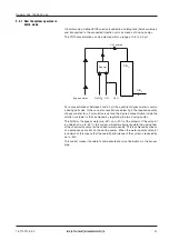
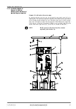
5.2.5 Bypass Line
The bypass water line dilutes the chlorine dioxide solution generated in the reactor
(approx. 20 g/l) and routes it to the main water flow.
Several versions of the bypass line are available:
❏
Bypass with solenoid valve and flow limiter
❏
Bypass with circulating pump and flow limiter
❏
Bypass with solenoid valve and dosing ball valve (batch mode)
❏
Bypass for external booster pump (see Section 14, Accessories, for booster
pump and load unit)
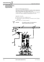
The water in the bypass is monitored by a flowmeter which switches the system off
if the bypass water falls below a minimum flow. Falling below the minimum water
quantity is also indicated by a flashing LED on the flowchart. The LED lights up
continuously if the water flow is above the minimum quantity (see Section "Control
and display elements on the controller", item 3).
The bypass lines with solenoid valve or internal/external booster pump are
equipped with a flow limiter. The flow is limited - independent of the input pressure
(1 to 10 bar) - to a max. water quantity of 420 l/h or 900 l/h, tolerance range +/- 10%.
The min. water quantity differs for each Oxiperm system, see also Section 3.1.1,
Performance and Consumption Data.
NOTE
Fit a particle filter upstream if the bypass water is not
free of solids.
5.2.6 Post-mixer
The chlorine dioxide solution is mixed with the bypass water in the post-mixer. The
systems are delivered as standard with a post-mixer.
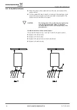
5.2.7 Purging Unit
Each Oxiperm C 164 for concentrated chemicals is fitted with a purging unit. A ball
valve is used for the standard systems. The reactor can therefore be filled with water
without problem prior to maintenance work. A purging unit with solenoid valve and
drain unit is also available as an option (see Section 5.1, System Design, items 15,
16). This drain unit also serves to automatically purge the reactor with water should
its temperature rise (with too little dilution water). When using a purging unit with
solenoid valve and drain unit, it is recommendable to directly connect the outlet
of the drain unit (solenoid valve) to a neutralization plant.
Summary of Contents for Oxiperm C 164 Series
Page 34: ...34 15 710010 V5 0 Oxiperm 164 150 2500 g en...
Page 96: ...96 15 710010 V5 0 Oxiperm 164 150 2500 g en...
Page 115: ......
Page 116: ......
Page 117: ......


