English (GB)
5
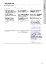
3. Installation
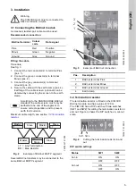
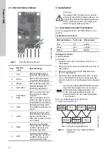
3.1 Connecting the BACnet module
A screened, twisted-pair cable must be used.
Recommended connection
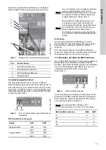
Fitting the cable
Procedure:
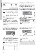
See fig.
.
1. Connect the red conductor(s) to terminal Plus
(pos. 1).
2. Connect the green conductor(s) to terminal
Minus (pos. 2).
3. Connect the grey conductor(s) to terminal
Ground (pos. 3).
4. Secure the cable with the earth clamp (pos. 4).
Earthing of the cable screen (optional) can be
obtained by connecting the screen to the earth
clamp.
Maximum cable length, see section
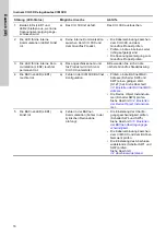
Fig. 2
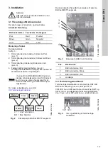
Example of BACnet MS/TP segment
Several BACnet masters may be connected to the
same BACnet MS/TP segment.
Fig. 3
Example of BACnet connection
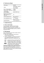
3.2 Termination resistor
The termination resistor is fitted on the CIM 3XX
BACnet module and has a value of 120
.
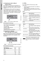
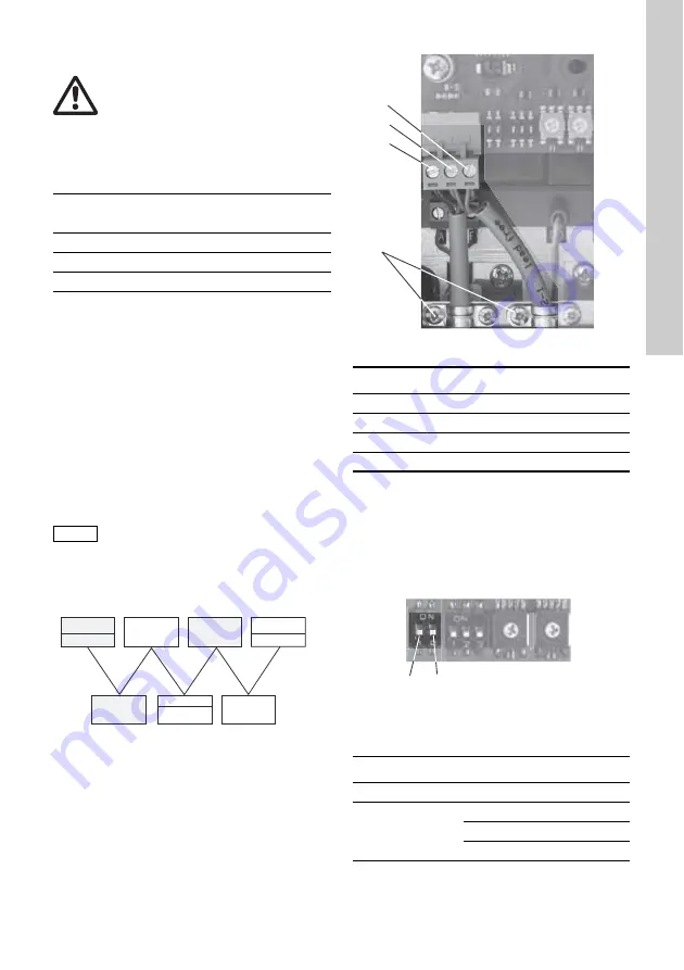
The CIM 3XX has a DIP switch with two switches
(SW1 and SW2) for cutting the termination resistor in
and out. Figure
shows the DIP switches in cut-out
state.
Fig. 4
Cutting the termination resistor in and
out
DIP switch settings
Warning
The CIM 3XX must only be connected to
SELV or SELV-E circuits.
BACnet terminal
Colour
code
Data signal
Plus
Red
Positive
Minus
Green
Negative
Ground
Grey
Ground
Note
According to the ANSI/ASHRAE BACnet
standard, the cable screen must only be
earthed at one end of the segment to
ensure correct operation and to prevent
earth fault currents.
TM
0
4
4
27
4 1
009
LT
BR
LT
LT = Line Termination
BR = Bias Resistor
Master
Master
Master
Slave
Slave
Slave
Slave
TM
04
5
059
25
0
9
Pos.
Description
1
BACnet terminal Plus
2
BACnet terminal Minus
3
BACnet terminal Ground
4
Earth clamp
TM
04
17
01
09
08
Status
SW1
SW2
Cut-in
ON
ON
Cut-out
OFF
OFF
ON
OFF
OFF
ON
2
3
1
4
SW1 SW2
Summary of Contents for CIM 3 Series
Page 1: ...CIM 300 BACnet module Installation and operating instructions GRUNDFOS INSTRUCTIONS...
Page 2: ...2...
Page 80: ...JP 80 8 1 2...
Page 84: ...84 1 RoHS W W W y K K K K K y K K K K K d K d y d...
Page 85: ...85...


