background image

46

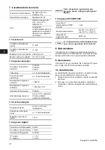
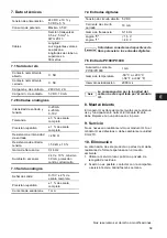
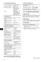
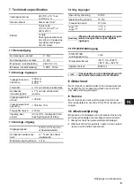
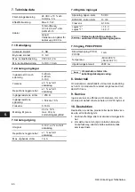
7. Características técnicas

7.1 Saída de relé

7.2 Entradas analógicas

7.3 Saída analógica

7.4 Entradas digitais

7.5 Entrada Pt100/Pt1000

8. Manutenção

O módulo IO é isento de manutenção durante a utili-
zação e o funcionamento normais. O módulo IO só 
pode ser limpo com um pano seco e sem poeiras.

9. Assistência

O módulo IO não pode ser reparado. Se o módulo IO 
avariar, a unidade CIU 27X tem de ser substituída.

10. Eliminação

Este produto ou as suas peças devem ser elimina-
das de forma ambientalmente segura:
1. Utilize o serviço de recolha de desperdícios 

público ou privado.

2. Se tal não for possível, contacte a Grundfos mais 

próxima de si ou oficina de reparação.

Tensão de alimentação

24 VCC ± 10 % e
5 VCC ± 5 %

Consumo de energia

Máximo 3,5 W

Cabos

Secção nominal:
0,5 a 2,5 mm

2

 ou 

AWG 20-13

Comprimento:
Os valores acima apli-
cam-se a cabos com 
comprimento não supe-
rior a 30 metros.

Contacto normalmente 
aberto

C, NO

Contacto normalmente 
fechado

C, NC

Carga máxima de con-
tacto

240 VCA, 2 A

Carga mínima de contacto 5 VCC, 10 mA

Corrente e tensão de 
entrada

0 - 20 mA
4 - 20 mA
0 - 10 V

Tolerância

± 3 % da escala total

Precisão repetitiva

± 1 % da escala total

Impedância, corrente

< 250 

Impedância, tensão

> 50 k

 ± 10 %

Gama de frequência

0-16 Hz

Alimentação do sensor

24 V ± 10 %, máximo 
30 mA, protecção 
contra curto-circuitos

Sinal de saída

0-10 V ± 2 % da 
escala total

Precisão repetitiva

± 1 % da escala total

Corrente máxima de saída

1 mA

Tensão em circuito aberto 5 VCC

Corrente em circuito 
fechado

10 mA

Gama de frequência

0-16 Hz

Lógica "0"
Lógica "1"

< 1,5 V
> 4,0 V

Atenção

Só podem ser ligados dispositivos 
livres de potencial às entradas digitais.

Corrente de alimentação 
Pt100/Pt1000

1 mA

Intervalo de temperatura

-50 °C a +200 °C
(-58 °F a +392 °F)

Intervalo de actualização

2000 mseg.

Nota

A compensação do comprimento do 
cabo não é suportada pelo módulo IO.

Sujeito a alterações.

Summary of Contents for CIU 27 Series

Page 1: ...Multi purpose IO module in CIU 27X GRUNDFOS INSTRUCTIONS Installation and operating instructions...

Page 2: ...108 CE Norma aplicada EN 61326 1 2006 Declara o de Conformidade A Grundfos declara sob sua nica responsabilidade que o produto M dulo IO ao qual diz respeito esta declara o est em conformidade com as...

Page 3: ...nstallation et de fonctionnement 19 Istruzioni di installazione e funzionamento 26 Instrucciones de instalaci n y funcionamiento 33 Instru es de instala o e funcionamento 40 Installatie en bedieningsi...

Page 4: ...erface 4 Installation We recommend you to carefully follow the order of installation below to ensure easy and correct installation Install the CIU 27X unit See installation and operating instructions...

Page 5: ...1 Analog input 1 or digital input 1 3 24 V supply for AI2 4 AI2 DI2 Analog input 2 or digital input 2 5 GND Earth terminal 6 AO Analog output 0 10 V 5 3 Analog output 7 GND Earth terminal 8 DI3 Digita...

Page 6: ...ol signal 0 20 mA analog control signal 4 20 mA digital control signal factory setting Fig 3 AI1 AI2 and DI1 DI2 For further information see section 6 Overview of inputs and outputs 5 2 1 Jumper setti...

Page 7: ...pos 13 is permanently green when the power supply has been switched on the power supply to the IO module is OK If the LED remains off after the power supply has been switched on see section 9 Service...

Page 8: ...mA C Common NC Normally closed contact Configurable inputs AI1 DI1 and AI2 DI2 IO module 1 24 V for AI1 24 V 10 maximum 30 mA short circuit protected or 2 AI1 DI1 0 20 mA 4 20 mA 0 10 V digital 3 24 V...

Page 9: ...ll scale Maximum output current 1 mA 7 GND Digital inputs IO module 8 DI3 Digital input 9 GND 10 DI4 Digital input Pt100 Pt1000 sensor input IO module 11 GND 12 Pt100 Pt1000 Terminal Designation Data...

Page 10: ...above values apply to cable lengths not exceeding 30 metres Normally open contact C NO Normally closed contact C NC Maximum contact load 240 VAC 2 A Minimum contact load 5 VDC 10 mA Input current and...

Page 11: ...wie z B Drehrichtungspfeil Kennzeichnung f r Fluidanschl sse m ssen unbedingt beachtet und in vollst ndig lesba rem Zustand gehalten werden 1 3 Personalqualifikation und schulung Das Personal f r Bedi...

Page 12: ...ellenge r t Das CIU 27X ist gleichzeitig ein Datenerfassungs und Kommunikationsger t Es ist bestimmt f r den Einsatz im Grundfos Remote Management System 3 Verwendungszweck Das CIU 27X enth lt zwei Mo...

Page 13: ...1 oder Digitaleingang 1 3 24 V Spannungsversorgung f r AI2 4 AI2 DI2 Analogeingang 2 oder Digitaleingang 2 5 GND Masseklemme 6 AO Analogausgang 0 10 V 5 3 Analogausgang 7 GND Masseklemme 8 DI3 Digita...

Page 14: ...ignal Werkseinstellung Abb 3 AI1 AI2 und DI1 DI2 Weitere Informationen hierzu siehe Abschnitt 6 bersicht ber die Ein und Ausg nge 5 2 1 Setzen der Kurzschlussbr cken Abb 4 Kurzschlussbr cken Konfigura...

Page 15: ...100 Pt1000 Eingang 5 6 Netzkontrollleuchte LED Siehe Abb 8 Wurde die Spannungsversorgung ordnungsgem hergestellt leuchtet die gr ne LED Pos 13 Leuchtet die gr ne LED nach dem Einschalten der Spannungs...

Page 16: ...re Eing nge AI1 DI1 und AI2 DI2 IO Modul 1 24 V f r AI1 24 V 10 maximal 30 mA kurzschlusssicher oder 2 AI1 DI1 0 20 mA 4 20 mA 0 10 V Digitalsignal 3 24 V f r AI2 24 V 10 maximal 30 mA kurzschlusssich...

Page 17: ...ert Maximaler Strom am Ausgang 1 mA 7 GND Digitaleing nge IO Modul 8 DI3 Digitaleingang 9 GND 10 DI4 Digitaleingang Pt100 Pt1000 Sensoreingang IO Modul 11 GND 12 Pt100 Pt1000 Klemme Bezeichnung Bemerk...

Page 18: ...AWG 20 13 Kabell nge Die oben angef hrten Werte gelten f r Kabel l ngen kleiner 30 m Schlie er C NO ffner C NC Max Kontaktlast 240 VAC 2 A Min Kontaktlast 5 VDC 10 mA Strom und Spannung am Eingang 0...

Page 19: ...ssous pour assurer une installation conforme et simple Installer l unit CIU 27X Consulter la notice d ins tallation et de fonctionnement de l unit CIU Connecter tous les conducteurs au module IO Voir...

Page 20: ...e 1 ou entr e digitale 1 3 Alimentation 24 V pour AI2 4 AI2 DI2 Entr e analogique 2 ou entr e digitale 2 5 GND Borne terre 6 AO Sortie analogique 0 10 V 5 3 Sortie analogique 7 GND Borne terre 8 DI3 E...

Page 21: ...ue 0 20 mA signal de commande analogique 4 20 mA signal de commande digital r glage par d faut Fig 3 AI1 AI2 et DI1 DI2 Pour plus d informations voir paragraphe 6 Aper u des entr es et sorties 5 2 1 R...

Page 22: ...le voyant pos 13 est allum vert en permanence apr s mise sous tension l alimentation lectrique au module IO est OK Si le voyant reste teint apr s mise sous tension voir paragraphe 9 Maintenance Fig 8...

Page 23: ...C Commune NC Contact normalement ferm Entr es configurables AI1 DI1 et AI2 DI2 Module IO 1 24 V pour AI1 24 V 10 maximum 30 mA protection court circuit ou 2 AI1 DI1 0 20 mA 4 20 mA 0 10 V digital 3 2...

Page 24: ...on maximale Intensit de sortie maxi 1 mA 7 GND Entr es digitales Module IO 8 DI3 Entr e digitale 9 GND 10 DI4 Entr e digitale Entr e capteur Pt100 Pt1000 Module IO 11 GND 12 Pt100 Pt1000 Borne D signa...

Page 25: ...es ci dessus s appli quent aux c bles ne d passant pas 30 m Contact normalement ouvert C NO Contact normalement ferm C NC Charge du contact maximum 240 VAC 2 A Charge du contact minimum 5 VDC 10 mA I...

Page 26: ...ntamente la sequenza riportata di seguito per garantire un installazione semplice e corretta Installare l unit CIU 27X Consultare le istruzioni di installazione e funzionamento dell unit CIU Collegare...

Page 27: ...tale 1 3 Alimentazione 24 V per AI2 4 AI2 DI2 Ingresso analogico 2 o Ingresso digitale 2 5 GND Morsetto di terra 6 AO Uscita analogica 0 10 V 5 3 Uscita analogica 7 GND Morsetto di terra 8 DI3 Ingress...

Page 28: ...controllo analogico 4 20 mA segnale di controllo digiale impostazione di fab brica Fig 3 AI1 AI2 e DI1 DI2 Per ulteriori informazioni vedere la sezione 6 Panoramica di ingressi e uscite 5 2 1 Impostaz...

Page 29: ...erde con l alimentazione elettrica inserita il modulo IO alimentato corretta mente Se il LED rimane spento anche con l alimentazione elettrica inserita vedere sezione 9 Assistenza Fig 8 Spia di funzio...

Page 30: ...Comune NC Contatto normalmente chiuso Ingressi configurabili AI1 DI1 e AI2 DI2 Modulo IO 1 24 V per AI1 24 V 10 massimo 30 mA protetto contro il cortocircuito oppure 2 AI1 DI1 0 20 mA 4 20 mA 0 10 V D...

Page 31: ...Corrente di uscita massima 1 mA 7 GND Ingressi digitali Modulo IO 8 DI3 Ingresso digitale 9 GND 10 DI4 Ingresso digitale Ingresso sensore Pt100 Pt1000 Modulo IO 11 GND 12 Pt100 Pt1000 Morsetto Denomin...

Page 32: ...nghezze del cavo non superiori a 30 metri Contatto normalmente aperto C NO Contatto normalmente chiuso C NC Massimo carico di contatto 240 VAC 2 A Minimo carico di contatto 5 V CC 10 mA Corrente e ten...

Page 33: ...4 Instalaci n Recomendamos seguir con atenci n los pasos de instalaci n indicados para asegurar una correcta y sencilla instalaci n Instalar la unidad CIU 27X Ver instrucciones de instalaci n y funcio...

Page 34: ...igital 1 3 24 V suministro para AI2 4 AI2 DI2 Entrada anal gica 2 o entrada digital 2 5 GND Terminal de tierra 6 AO Salida anal gica 0 10 V 5 3 Salida anal gica 7 GND Terminal de tierra 8 DI3 Entrada...

Page 35: ...ol 0 20 mA se al anal gica de control 4 20 mA se al digital de control ajuste de f brica Fig 3 AI1 AI2 y DI1 DI2 Para informaci n adicional ver la secci n 6 Resumen de entradas y salidas 5 2 1 Ajuste...

Page 36: ...do el suministro el ctrico el suministro el ctrico del m dulo IO funciona correctamente Si el LED permance apagado cuando se conecta el suministro el ctrico ver la secci n 9 Servicio Fig 8 LED indicad...

Page 37: ...C Com n NC Contacto normalmente cerrado Entradas configurables AI1 DI1 y AI2 DI2 M dulo IO 1 24 V para AI1 24 V 10 m ximo 30 mA protecci n contra cortocircuito o 2 AI1 DI1 0 20 mA 4 20 mA 0 10 V digi...

Page 38: ...pleta Intensidad m x de salida 1 mA 7 GND Entradas digitales M dulo IO 8 DI3 Entrada digital 9 GND 10 DI4 Entrada digital Entrada sensor Pt100 Pt1000 M dulo IO 11 GND 12 Pt100 Pt1000 Terminal Denomina...

Page 39: ...longitudes de clabe no superiores a 30 metros Contacto normalmente abierto C NO Contacto normalmente cerrado C NC Carga m x de contacto 240 VAC 2 A Carga m n de contacto 5 VDC 10 mA Intensidad de entr...

Page 40: ...e a ordem de instala o que se segue para assegurar uma ins tala o f cil e correcta Instale a unidade CIU 27X Consulte as instru es de instala o e funcionamento para a uni dade CIU Ligue todos os condu...

Page 41: ...rada digital 1 3 Alimenta o de 24 V para AI2 4 AI2 DI2 Entrada anal gica 2 ou entrada digital 2 5 GND Borne de terra 6 AO Sa da anal gica 0 10 V 5 3 Sa da anal gica 7 GND Borne de terra 8 DI3 Entrada...

Page 42: ...sinal de controlo anal gico 4 20 mA sinal de controlo digital configura o de f brica Fig 3 AI1 AI2 e DI1 DI2 Para mais informa es consulte a sec o 6 Descri o geral das entradas e sa das 5 2 1 Configu...

Page 43: ...Consulte a fig 8 Se o LED posi o 13 ficar permanentemente verde quando a alimenta o tiver sido ligada a alimenta o do m dulo IO est OK Se o LED continuar apagado depois de a alimenta o ter sido ligada...

Page 44: ...mA C Comum NC Contacto normalmente fechado Entradas configur veis AI1 DI1 e AI2 DI2 M dulo IO 1 24 V para AI1 24 V 10 m ximo 30 mA protec o contra curto circuitos ou 2 AI1 DI1 0 20 mA 4 20 mA 0 10 V d...

Page 45: ...otal Corrente m xima de sa da 1 mA 7 GND Entradas digitais M dulo IO 8 DI3 Entrada digital 9 GND 10 DI4 Entrada digital Entrada de sensor Pt100 Pt1000 M dulo IO 11 GND 12 Pt100 Pt1000 Terminal Designa...

Page 46: ...pli cam se a cabos com comprimento n o supe rior a 30 metros Contacto normalmente aberto C NO Contacto normalmente fechado C NC Carga m xima de con tacto 240 VCA 2 A Carga m nima de contacto 5 VCC 10...

Page 47: ...udige en correcte installatie Installeer de CIU 27X unit Zie de installatie en bedieningsinstructies voor de CIU unit Verbind alle relevante geleiders met de IO module Zie paragraaf 5 IO module Verbin...

Page 48: ...ge ingang 1 voor digitale ingang 1 3 24 V voeding voor AI2 4 AI2 DI2 Analoge ingang 2 of digitale ingang 2 5 GND Aardeklem 6 AO Analoge uitgang 0 10 V 5 3 Analoge uitgang 7 GND Aardeklem 8 DI3 Digital...

Page 49: ...ingssignaal 0 20 mA analoog besturingssignaal 4 20 mA digitaal besturingssignaal fabrieksinstelling Afb 3 AI1 AI2 en DI1 DI2 Voor meer informatie zie paragraaf 6 Overzicht van ingangen en uitgangen 5...

Page 50: ...e LED pos 13 constant groen is wanneer de voedingspanning is ingeschakeld is de voedings spanning naar de IO module correct Als de LED niet gaat branden nadat de voedings spanning is ingeschakeld zie...

Page 51: ...rmaal gesloten contact Te configureren ingangen AI1 DI1 en AI2 DI2 IO module 1 24 V voor AI1 24 V 10 maximaal 30 mA beveiligd tegen kortsluiting of 2 AI1 DI1 0 20 mA 4 20 mA 0 10 V digitaal 3 24 V voo...

Page 52: ...e schaaleindwaarde Maximale uitgangsstroom 1 mA 7 GND Dig ingangen IO module 8 DI3 Dig ingang 9 GND 10 DI4 Dig ingang Pt100 Pt1000 sensoringang IO module 11 GND 12 Pt100 Pt1000 Klem Aanduiding Gegeven...

Page 53: ...kabels niet langer dan 30 meter Normaal open contact C NO Normaal gesloten contact C NC Maximale contactbelasting 240 VAC 2 A Minimale contactbelasting 5 VDC 10 mA Ingangsstroom en spanning 0 20 mA 4...

Page 54: ...las in eller aktiveras fr n webbanv ndargr ns snittet i Grundfos Remote Management 4 Installation F lj installationsanvisningarna nedan f r enkel och korrekt installation Installera enheten CIU 27X Se...

Page 55: ...er Digital ing ng 1 3 24 V sp nningsf rs rjning f r AI2 4 AI2 DI2 Analog ing ng 2 eller Digital ing ng 2 5 GND Jordplint 6 AO Analog utg ng 0 10 V 5 3 Analog utg ng 7 GND Jordplint 8 DI3 Digital ing n...

Page 56: ...alog styrsignal 4 20 mA digital styrsignal fabriksinst llning Fig 3 AI1 AI2 och DI1 DI2 Mer information finns i avsnitt 6 versikt ver in och utg ngar 5 2 1 Byglingsinst llningar Fig 4 Byglingar Konfig...

Page 57: ...Om lampan pos 13 lyser gr n n r sp nningsf r s rjningen slagits till fungerar sp nningsf rs rj ningen till IO modulen korrekt Se avsnitt 9 Service om lampan f rblir sl ckt efter att sp nningsf rs rjni...

Page 58: ...emensam NC Brytande kontakt Konfigurerbara ing ngar AI1 DI1 och AI2 DI2 IO modul 1 24 V f r AI1 24 V 10 max 30 mA kortslutningsskyddad eller 2 AI1 DI1 0 20 mA 4 20 mA 0 10 V digital 3 24 V f r AI2 24...

Page 59: ...t skalutslag Max utg ende str m 1 mA 7 GND Digitala ing ngar IO modul 8 DI3 Digital ing ng 9 GND 10 DI4 Digital ing ng Ing ng f r Pt100 Pt1000 sensor IO modul 11 GND 12 Pt100 Pt1000 Plint Ben mning Da...

Page 60: ...r AWG 20 13 L ngd V rdena ovan g ller f r kablar upp till 30 m Slutande kontakt C NO Brytande kontakt C NC Max kontaktbelastning 240 VAC 2 A Min kontaktbelastning 5 VDC 10 mA Ing ende str m och sp nni...

Page 61: ...ement web brugerinterface 4 Installation Vi anbefaler at f lge nedenst ende installations r kkef lge n je for at sikre let og korrekt installa tion Install r CIU 27X enheden Se monterings og driftsins...

Page 62: ...eller digital indgang 1 3 24 V forsyning til AI2 4 AI2 DI2 Analog indgang 2 eller digital indgang 2 5 GND Jordklemme 6 AO Analog udgang 0 10 V 5 3 Analog udgang 7 GND Jordklemme 8 DI3 Digital indgang...

Page 63: ...t styresignal 0 20 mA analogt styresignal 4 20 mA digitalt styresignal fabriksindstilling Fig 3 AI1 AI2 og DI1 DI2 For yderligere oplysninger se afsnit 6 Oversigt over ind og udgange 5 2 1 Jumperindst...

Page 64: ...oden pos 13 lyser konstant gr nt n r der er t ndt for str mforsyningen er str mforsyningen til IO modulet i orden Hvis lysdioden forbliver slukket efter at der er t ndt for str mforsyningen se afsnit...

Page 65: ...NC Brydekontakt Konfigurerbare indgange AI1 DI1 og AI2 DI2 IO modul 1 24 V til AI1 24 V 10 maks 30 mA kortslutningsbeskyttet eller 2 AI1 DI1 0 20 mA 4 20 mA 0 10 V digital 3 24 V til AI2 24 V 10 maks...

Page 66: ...a Maks udgangsstr m 1 mA 7 Jord GND Digitale indgange IO modul 8 DI3 Digital indgang 9 Jord GND 10 DI4 Digital indgang Pt100 Pt1000 sensorindgang IO modul 11 Jord GND 12 Pt100 Pt1000 Klemme Betegnelse...

Page 67: ...rdier g lder for kabell ngder til og med 30 meter Sluttekontakt C NO Brydekontakt C NC Maks kontaktbelastning 240 VAC 2 A Min kontaktbelastning 5 VDC 10 mA Indgangsstr m og sp nding 0 20 mA 4 20 mA 0...

Page 68: ...69 1 6 69 1 7 69 1 8 69 1 9 69 2 69 3 70 4 70 5 70 5 1 70 6 IO 71 6 1 72 6 2 AI1 DI1 AI2 DI2 72 6 3 73 6 4 73 6 5 Pt100 Pt1000 73 6 6 73 7 74 8 75 8 1 75 8 2 S 75 8 3 75 8 4 76 8 5 Pt100 Pt1000 76 9 7...

Page 69: ...69 1 3 1 4 1 5 1 6 1 7 1 8 1 9 2 15150...

Page 70: ...ce Unit CIU 27X CIU 27X Grundfos Remote Management 4 CIU 27X GSM CIM 27X IO GSM CIM 27X GSM CIM 2XX IO Grundfos Remote Management IO Grundfos Remote Management 5 Grundfos CIU 27X CIU IO 6 IO GSM SIM G...

Page 71: ...6 7 8 9 10 1112 NC 13 14 NO NO 6 1 C C NC NC 1 24 AI1 6 2 AI1 DI1 AI2 DI2 2 AI1 DI1 1 1 3 24 AI2 4 AI2 DI2 2 2 5 GND 6 AO 0 10 6 3 7 GND 8 DI3 3 6 4 9 GND 10 DI4 4 11 GND 6 5 Pt100 Pt1000 12 Pt100 Pt...

Page 72: ...6 2 AI1 DI1 AI2 DI2 IO 1 2 4 0 10 0 20 4 20 3 AI1 AI2 DI1 DI2 7 6 2 1 4 AI1 DI1 AI2 DI2 TM04 3974 0509 NO C NC TM04 4032 0509 NO C NC AI1 AI2 DI1 DI2 GND TM04 3975 0509 J1 J2 0 10 0 20 4 20 J3 J4 0 10...

Page 73: ...gement 5 7 5 6 4 IO 6 7 6 DI3 DI4 6 5 Pt100 Pt1000 IO Pt 7 7 7 Pt100 Pt1000 6 6 8 13 IO 10 8 CIU TM04 3985 0509 CIU TM04 3986 0509 6 7 0 10 8 9 10 DI3 DI4 CIU TM04 3987 0509 IO TM04 3988 0509 11 12 PT...

Page 74: ...AO C DI NC NO IO NO 240 2 A 5 10 C NC AI1 DI1 AI2 DI2 IO 1 24 AI1 24 10 30 2 AI1 DI1 0 20 A 4 20 A 0 10 3 24 AI2 24 10 30 4 AI2 DI2 0 20 A 4 20 A 0 10 5 GND 6 2 1 NO C NC 1 2 3 4 5 AI1 AI2 1 2 3 4 5...

Page 75: ...2 1 7 GND IO 8 DI3 9 GND 10 DI4 Pt100 Pt1000 IO 11 GND 12 Pt100 Pt1000 6 7 DI3 DI4 8 9 10 Pt100 Pt1000 11 12 24 DC 10 5 DC 5 3 5 0 5 2 5 2 AWG 20 13 30 C NO C NC 240 2 A 5 10 0 20 A 4 20 A 0 10 3 1 25...

Page 76: ...76 8 4 8 5 Pt100 Pt1000 9 IO IO 10 IO IO CIU 27X 11 1 2 Grundfos 12 24 Grundfos 5 DC 10 0 16 0 1 1 5 4 0 Pt100 Pt1000 1 50 C 200 C 2000 IO...

Page 77: ...le tirilebilir 4 Kurulum Kolay ve do ru kurulumu sa lamak i in a a daki kurulum talimat n dikkatlice uygulaman z neririz CIU 27X nitesini kurun CIU unitesi kurulum ve al ma talimatlar na bak n z T m i...

Page 78: ...g giri 1 veya dijital giri 1 3 AI2 i in 24 V lik kaynak 4 AI2 DI2 Analog giri 2 veya dijital giri 2 5 GND Toprak terminali 6 AO Analog k 0 10 V 5 3 Analog k 7 GND Toprak terminali 8 DI3 Dijital giri 3...

Page 79: ...V analog kontrol sinyali 0 20 mA analog kontrol sinyali 4 20 mA dijital kontrol sinyali fabrika ayar ekil 3 AI1 AI2 ve DI1 DI2 Daha fazla bilgi i in b l m 6 Giri ve k lara genel bak e bak n z 5 2 1 B...

Page 80: ...stergesi LED Bak n z ekil 8 G kayna a ld nda LED konum 13 s rekli ye ilse IO mod l ne giden g kayna problemsizdir G kayna a ld ktan sonra LED kapal kal yorsa b l m 9 Servis e bak n z ekil 8 G g sterg...

Page 81: ...el NC Normalde kapal kontak AI1 DI1 ve AI2 DI2 ayarlanabilir giri leri IO mod l 1 AI1 i in 24 V 24 V 10 maksimum 30 mA k sa devre korumal veya 2 AI1 DI1 0 20 mA 4 20 mA 0 10 V dijital 3 AI2 i in 24 V...

Page 82: ...n 0 10 V 2 si Maksimum k ak m 1 mA 7 GND Dijital giri ler IO mod l 8 DI3 Dijital giri 9 GND 10 DI4 Dijital giri Pt100 Pt1000 sens r giri i IO mod l 11 GND 12 Pt100 Pt1000 Terminal G sterim Veri ema 6...

Page 83: ...20 13 Uzunluk Yukar daki de erler 30 metreyi a mayan kablo uzunluklar na uyumludur Normalde a k kontak C NO Normalde kapal kontak C NC Maksimum kontak y k 240 VAC 2 A Minimum kontak y k 5 VDC 10 mA G...

Page 84: ...R K Bah e Mah 126 Cadde No 5 D MERS N 0324 233 58 91 0324 233 58 91 0533 300 07 99 DETAY M HEND SL K Prof Muammer Aksoy Cadde Tanerler Apt No 25 SKENDERUN 0326 614 68 56 0326 614 68 57 0533 761 73 50...

Page 85: ...510 994 12 4992 462 994 50 2040 561 BARI BOB NAJ Ziya akalp Cadde No 13 A MAGOSA K K T C 0392 366 95 55 0533 866 76 82 THERM ARSENAL Tsereteli Ave 101 0119 TB L S GEORGIA 995 32 35 62 01 995 32 35 62...

Page 86: ...7 92 7 1 92 7 2 92 7 3 92 7 4 92 7 5 Pt100 Pt1000 92 8 92 9 92 10 92 1 2 CIU 27X IO CIU Communication Interface Unit CIU 27X CIU 27X Grundfos Remote Management system 3 CIU 27X CIM 27X GSM IO I O CIM...

Page 87: ...9 10 1112 NC 13 14 NO NO 5 1 C C NC NC 1 AI1 24 V 5 2 AI1 DI1 AI2 DI2 2 AI1 DI1 1 1 3 AI2 24 V 4 AI2 DI2 2 2 5 GND 6 AO 0 10 V 5 3 7 GND 8 DI3 3 5 4 9 GND 10 DI4 4 11 GND 5 5 Pt100 Pt1000 12 Pt100 Pt...

Page 88: ...AI2 DI2 IO 1 2 4 0 10 V 0 20 mA 4 20 mA 3 AI1 AI2 DI1 DI2 6 5 2 1 4 AI1 DI1 AI2 DI2 TM04 3974 0509 NO C NC TM04 4032 0509 TM04 3975 0509 NO C NC AI1 AI2 DI1 DI2 GND J1 J2 J3 J4 J1 J2 0 10 V 0 20 mA 4...

Page 89: ...6 5 5 4 IO 6 6 6 DI3 DI4 5 5 Pt100 Pt1000 IO Pt 7 6 7 Pt100 Pt1000 5 6 LED 8 LED 13 IO LED 9 8 LED CIU TM04 3985 0509 CIU TM04 3986 0509 6 7 0 10 V 8 9 10 DI3 DI4 CIU TM04 3987 0509 IO TM04 3988 0509...

Page 90: ...NO 240 VAC 2 A 5 VDC 10 mA C NC AI1 DI1 AI2 DI2 IO 1 AI1 24 V 24 V 10 30 mA 2 AI1 DI1 0 20 mA 4 20 mA 0 10 V 3 AI2 24 V 24 V 10 30 mA 4 AI2 DI2 0 20 mA 4 20 mA 0 10 V 5 GND 5 2 1 NO C NC 1 2 3 4 5 AI...

Page 91: ...91 IO 6 AO 0 10 V 2 1 mA 7 GND IO 8 DI3 9 GND 10 DI4 Pt100 Pt1000 IO 11 GND 12 Pt100 Pt1000 6 7 DI3 DI4 8 9 10 Pt100 Pt1000 11 12...

Page 92: ...27X 10 1 2 24 VDC 10 5 VDC 5 3 5 W 0 5 2 5 mm2 AWG 20 13 30 C NO C NC 240 VAC 2 A 5 VDC 10 mA 0 20 mA 4 20 mA 0 10 V 3 1 250 50 k 10 0 16 Hz 24 V 10 30 mA 0 10 V 2 1 1 mA 5 VDC 10 mA 0 16 Hz 0 1 1 5 V...

Page 93: ...anda Shiagawa ku Tokyo 141 0022 Japan Phone 81 35 448 1391 Telefax 81 35 448 9619 Korea GRUNDFOS Pumps Korea Ltd 6th Floor Aju Building 679 5 Yeoksam dong Kangnam ku 135 916 Seoul Korea Phone 82 2 531...

Page 94: ...www grundfos com Being responsible is our foundation Thinking ahead makes it possible Innovation is the essence 96900420 0210 339 Repl 96900420 0409...

Reviews: