8
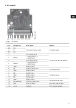
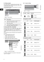
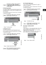
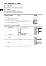
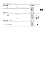
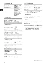
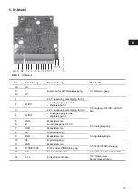
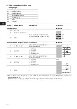
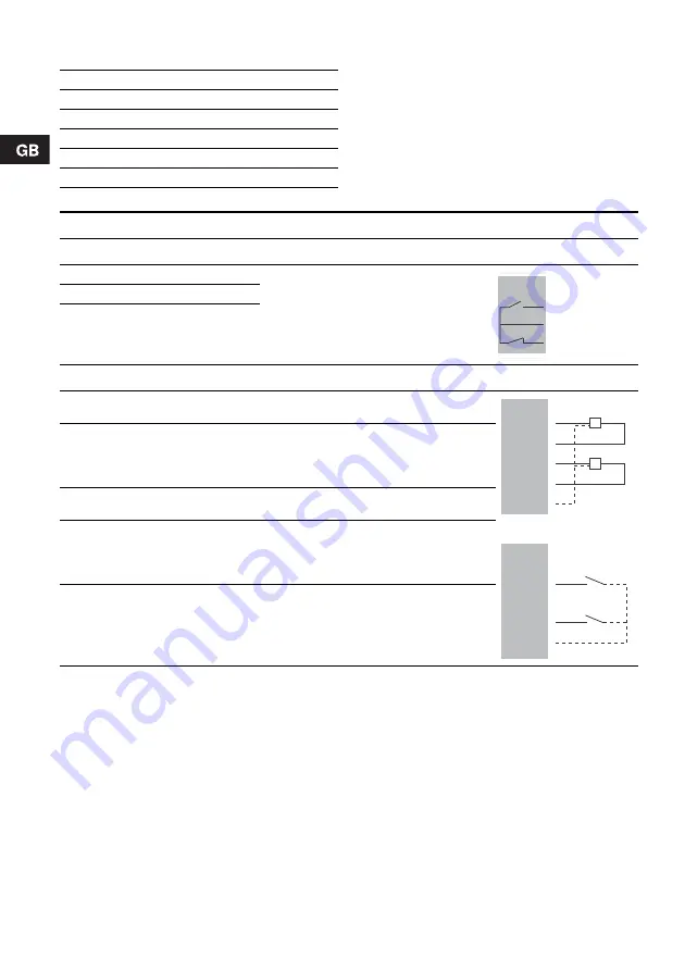
6. Overview of inputs and outputs
AI
Analog input
AO
Analog output
C
Common
DI
Digital input
NC
Normally closed contact
NO
Normally open contact
Terminal
Designation
Data
Diagram
Relay output
IO module
NO
Normally open contact
Maximum contact load: 240 VAC, 2 A
Minimum contact load: 5 VDC, 10 mA
C
Common
NC
Normally closed contact
Configurable inputs AI1/DI1* and AI2/DI2*
IO module
1
+ 24 V for AI1
24 V ± 10 %, maximum 30 mA,
short-circuit-protected
or
2
AI1/DI1
• 0-20 mA
• 4-20 mA
• 0-10 V
• digital
3
+ 24 V for AI2
24 V ± 10 %, maximum 30 mA,
short-circuit-protected
4
AI2/DI2
• 0-20 mA
• 4-20 mA
• 0-10 V
• digital
5
GND
-
* Configure these inputs by use of jumpers. See section 5.2.1 Jumper settings.
Note: Each input is to be configured according to the sensor connected.
NO
C
NC
1
2
3
4
5
AI1
AI2
1
2
3
4
5
DI1
DI2


